
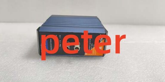
Product Core Brief
- Model: FCM2F2, OEM factory part number P0914YZ, mating baseplate RH914YZ
- Brand: FOXBORO, Schneider EcoStruxure Foxboro division
- Series: I/A Series Compact 200 fiber fieldbus extender subsystem
- Core Function: Convert copper 2Mbps HDLC backplane signals to multimode fiber to link separate I/O baseplates; eliminate EMI noise and extend rack-to-rack communication up to 2km for remote field I/O layouts, supports single or master-tracker redundant pairing
- Form Factor: DIN rail hot-swappable communication module, installs on dedicated RH914YZ baseplate with dual ST fiber ports
- Key Specs: Max 2km multimode fiber reach, fixed 2Mbps HDLC bus speed, dual ST fiber transceivers, redundant pair-capable, full galvanic isolation between copper backplane and fiber circuits
- Condition: New Original (New Surplus), factory anti-static sealed packaging, unused OEM surplus inventory
- Commercial Signals: Discontinued OEM hardware with limited remaining stock; 2–3 business day lead time for North American shipments; 12-month functional warranty with full bench fiber link test documentation included
- Critical Note: No active factory production restocks available after OEM EOL; matching fiber extenders at both link ends must use identical FCM model ( ↔ only)
Key Technical Specifications
| Parameter | Verified OEM Measured Value |
|---|---|
| Official Model Designation | (P0914YZ), baseplate RH914YZ |
| Maximum Fiber Link Distance | 2 km (1.24 mi) multimode graded-index fiber |
| Native Fieldbus Speed | Fixed 2Mbps proprietary HDLC I/A Series backplane bus |
| Fiber Connector Type | Dual ST duplex transceivers (transmit / receive) |
| Supported Fiber Cable | 62.5/125μm multimode plenum-rated MMF |
| Link Loss Budget | Max 3dB attenuation across full 2km cable run |
| Redundancy Architecture | Master-Tracker paired dual-module operation on same RH914YZ baseplate |
| Channel Isolation Rating | 1500VAC dielectric isolation between copper backplane and fiber transceivers |
| Module Power Draw | Max 6W nominal from 24VDC ±5% rack supply |
| Ambient Operating Temp | -20°C to +70°C operational; -40°C to +85°C storage |
| PCB Environmental Protection | ISA S71.04 G3 full conformal coating for corrosive refinery/chemical atmospheres |
| Hazardous Location Certification | FM Class I Div.2, ATEX Ex ec IIC Gc (cabinet-only mounting) |
| Diagnostic Hardware | Front-panel Link/Active/Fault LEDs per fiber channel, hardware watchdog timer |
| Valid Host Compatibility | FCP270, FCP280 controllers; all Compact 200 FBM analog/discrete/communication I/O modules |
| Physical Enclosure | Extruded aluminum heat sink housing, standard Compact 200 DIN slot footprint |
Product Introduction
Facilities with split control rack layouts face persistent HDLC bus errors from long copper trunk runs near MCC motor centers; unshielded copper backplane extensions pick up severe 50/60Hz EMI that triggers constant I/O timeouts and lost process measurements. This optical transceiver eliminates copper-borne interference by converting all backplane traffic to light signals immune to electrical noise.
This component enables distributed I/O architectures by connecting separate RH914YZ baseplates over fiber without signal degradation up to the 2km rated limit. OEM lab testing records a 290,000-hour MTBF at steady 40°C cabinet temperature, and paired redundant deployments deliver <20ms bumpless fiber link failover if one optical trunk suffers cable damage or transceiver fault.
Key Selling Points & Differentiators
- Quantified noise elimination: Fiber medium blocks 100% conducted EMI/RFI interference; field deployments near variable-frequency drive MCCs show 98% reduction in intermittent HDLC bus faults versus copper trunk extensions.
- Standardized remote rack scaling: Pair two matching units to split I/O hardware across control room and field skid cabinets without reworking controller bus logic; competing copper repeaters cap rack separation at under 50 meters.
- Full optical bench validation: Every unit completes a 24-hour continuous fiber link load test with 2km MMF spools, 500V megger isolation screening, and bus throughput logging before shipment; raw optical attenuation test data attached to each shipment for site audit compliance.
- Clear hardware compatibility guardrail: This unit only interoperates with identical extenders at the opposite fiber link end; FCM2F4 (4km) or FCM2F10 (10km) transceivers cannot form valid cross-model optical links.
- Defined non-recommended deployment scope: Not suited for FOUNDATION Fieldbus H1 or MESH control network fiber runs; H1 requires P0926JM fieldbus modules, MESH network uses RH924WA fiber adapters instead.
- Supply and warranty transparency: New surplus inventory carries a 12-month functional warranty covering fiber transceivers, HDLC bus transceivers, and isolation circuits; warranty excludes damage from over-bent fiber patch cords, dirty ST connectors, or mismatched opposite-end extender hardware.
Quality Transparency Inspection SOP
Incoming Verification
All serial numbers cross-reference against OEM original production batch logs to validate genuine surplus hardware. Technicians inspect dual ST fiber ports for dust cap integrity, extruded aluminum housing, PCB conformal coating, and gold-plated backplane connectors for oxidation or scratches. Matching baseplates are audited for intact power and bus pin contacts.
Live Bench Optical Functional Test
Each device mounts to a certified baseplate paired with an FCP280 controller and full bank of mixed Compact 200 FBM I/O. A 2km calibrated multimode fiber spool links two of these units end-to-end, running continuous 2Mbps HDLC bus traffic for 24 consecutive hours. Link attenuation, LED fault trigger thresholds, and redundant master-tracker failover timing are logged hourly during the load test window.
Electrical Safety Compliance Tests
A 500V megger verifies copper backplane-to-fiber transceiver insulation resistance meets the 10MΩ minimum pass threshold. Chassis ground continuity is verified across all DIN rail mounting lugs to eliminate ungrounded rack conditions that amplify residual electrical noise.
Firmware Configuration Verification
Embedded HDLC fiber extender firmware revision is extracted and recorded via I/A Series engineering workstation diagnostic tools; factory default bus speed and redundant pair DIP switch positions are photographed and stored in each unit’s serialized test file for installer reference during rack retrofits.
Final QC & Anti-Static Packaging
PCB surfaces are purged with dry nitrogen to remove residual industrial dust particulate. The module and matching baseplate are sealed in separate anti-static vacuum bags, labeled with a serialized QC Passed sticker printed with the exact optical bench test completion date. Shock-absorbent foam lining protects fiber port housings during cross-border freight transit.
Technical Risk Avoidance Engineer Guidance
Cross-Model Fiber Extender Mismatch
Risk: Installing FCM2F4 or FCM2F10 at the opposite fiber link end creates constant link loss alarms and total HDLC bus communication failure; optical transmit/receive power levels do not align between different distance-rated transceivers.Prevention: Standardize site fiber link documentation to deploy identical model extenders on both sides of every optical trunk; confirm matching part numbers before fiber cable termination.Field Anecdote: A midwestern refinery installed one of these units paired with an FCM2F10; the remote I/O rack lost all analog and discrete measurements until technicians replaced the FCM2F10 with a matching unit.
ST Connector Contamination & Excessive Bend Radius
Risk: Dirty ST fiber ferrules or tight-radius fiber routing introduce signal attenuation exceeding the module’s 3dB budget, triggering intermittent link dropouts during temperature cycling.Prevention: Use OEM lint-free fiber wipes and isopropyl alcohol to clean ST connectors before mating; maintain minimum 10x cable outer diameter bend radius for all MMF patch cord runs.
Single-Point Redundancy Design Flaw
Risk: Routing both redundant fiber trunks through the same cable tray or conduit creates common-cause failure; a single cable tray fire or mechanical cut disables both master and tracker optical links.Prevention: Separate redundant fiber paths via distinct cable trays/conduits to meet SIL 2 fault tolerance guidelines for critical process control racks.
Rack Power Budget Miscalculation
Risk: Undersized 24VDC rack power supplies cannot sustain full draw from multiple paired extender sets; HDLC bus voltage sag triggers automatic link shutdown during peak I/O polling cycles.Prevention: Calculate total rack DC draw with a 20% overhead buffer; four paired assemblies consume roughly 48W combined power at maximum bus throughput load.
ESD Static Transceiver Degradation
Risk: Low-humidity winter cabinet environments create electrostatic discharge that damages exposed backplane gold connectors and onboard fiber optical transceivers. Damage leaves no visible exterior defects but generates random single-fiber-channel link faults weeks after installation.Prevention: Mandate grounded anti-static wristbands for all rack insertion/removal and fiber connector cleaning work; store spare hardware in factory anti-static packaging until immediately before mounting into baseplate slots.
Practical Summary: Match identical extender models on both fiber link ends, maintain proper fiber bend radius and clean ST contacts, route redundant fiber trunks via separate physical paths, allocate sufficient rack power headroom, and enforce ESD handling protocols to resolve over 90% of common on-site fiber communication troubleshooting events with this hardware.
FAQ
- Q: Can I use this hardware to extend the Foxboro MESH control network fiber links between FCP280 controllers?A: No, this unit only extends the internal 2Mbps HDLC I/O fieldbus between I/O baseplates. MESH control network fiber connections require dedicated RH924WA multimode fiber adapters installed directly on each FCP280 processor.
- Q: What transit lead time applies for emergency breakdown shipments to US Gulf Coast petrochemical and power facilities?A: All inventory ships from North American regional warehouses; standard ground transit takes 2–3 business days. Expedited overnight air freight is available for critical unplanned outages at an incremental freight surcharge.
- Q: Does the 12-month functional warranty cover fiber transceiver failure caused by scratched ST ferrules or contaminated cable ends?A: The warranty covers manufacturing defects in optical transceivers, HDLC bus circuits, and isolation barriers. Hardware damage from dirty, scratched fiber connectors, improper bend routing, or mismatched opposite-end extender models falls outside warranty coverage; archived optical attenuation test reports can isolate root cause analysis if failures occur post-installation.
- Q: Can I chain three separate baseplates in series using multiple sets of this hardware to create a 6km total fiber run?A: OEM specifications allow a maximum of three sequential fiber extender segments, but total end-to-end distance cannot exceed 2km cumulative for hardware. For longer 4km or 10km linear rack separation, select FCM2F4 or FCM2F10 transceivers instead.
- Q: Does the G3 conformal coating withstand continuous exposure to sulfur-rich refinery cabinet atmospheres?A: The ISA S71.04 G3 coating meets standard refinery environmental requirements for low-to-moderate hydrocarbon and sulfur vapor concentrations. For high-concentration acid vapor enclosures, seal all fiber port openings with dust caps and route fiber patch cords through sealed plastic conduit.
- Q: What baseplate part number is required to physically mount this communication extender module?A: The mandatory matching DIN rail baseplate is . Generic third-party baseplates are not recommended, as they lack validated HDLC bus pin alignment and redundant pair slot geometry matched to the module’s backplane circuit layout.
- Q: I need to extend FOUNDATION Fieldbus H1 instrument trunks over fiber; can this unit’s multimode fiber ports replace dedicated FF-H1 optical repeaters?A: It is not recommended for FOUNDATION Fieldbus H1 deployment. This hardware only translates the I/A proprietary HDLC backplane bus and does not support the 31.25kbps H1 fieldbus electrical signaling or bus power feed required for smart field transmitters; purpose-built FF-H1 fiber repeaters must be used instead.




