
Product Core Brief
- Model: RH924YF
- Brand: FOXBORO (Schneider Electric EcoStruxure Foxboro)
- Series: I/A Series & Foxboro Evo FCP280 Controller Mount Infrastructure
- Core Function: Host single or master-tracker redundant FCP280 processors, fieldbus ports, and MESH network fiber/copper adapters on DIN rail racks
- Product Type: Vertical DIN rail modular controller baseplate assembly
- Key Specs: Dual FCP280 slot capacity | Four redundant A/B HDLC PIO fieldbus ports | Dual network adapter bays | ⚠️ EOL — limited stock remaining, Condition: New Surplus Original
Product Introduction
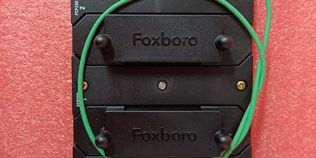
FOXBORO is a vertical DIN rail baseplate engineered exclusively to mount one or a fault-tolerant paired set of FCP280 field control processors for I/A Series DCS. It integrates hardwired redundant 2 Mbps HDLC fieldbus connectors and dedicated slots for RH924WA fiber or RH924UQ copper network adapters.This unit differs from single-position RH924YA baseplates by supporting full master-tracker redundant controller pairing, with OEM-measured MTBF of 340,000 hours at 40 °C cabinet ambient. Internal bus termination jumpers eliminate external resistors for Compact 200-series FBM trunk wiring.
Key Technical Specifications
| Parameter | Value |
|---|---|
| Controller Slot Capacity | Two vertical slots for processors (single or redundant master-tracker pairing) |
| Network Adapter Bays | Dual slots for RH924WA multimode fiber or RH924UQ copper Ethernet adapters |
| Fieldbus PIO Channels | Four independent A/B redundant HDLC fieldbus ports (2 Mbps / 268 kbps selectable) |
| Bus Termination Hardware | Onboard DIP switch termination for Fieldbus Port 1; ports 2–4 factory internally terminated |
| Operating Supply Voltage | 24 V DC ±5 %, max combined draw 14 W fully populated |
| Connector Construction | Gold-plated multi-pin backplane fieldbus and Ethernet header contacts |
| Mechanical Mounting | Standard 35 mm DIN rail vertical cabinet installation, IP20 cabinet-only rating |
| Operating Temperature Range | -20 °C to +70 °C operational; -40 °C to +85 °C storage |
| Environmental Coating | ISA S71.04 G3 full conformal PCB coating for corrosive plant gas atmospheres |
| Hazardous Certifications | FM Class I Div.2, ATEX Ex ec IIC Gc (cabinet enclosure mounting only) |
| Supported I/O Hardware | All Compact 200-series FBMs; 100-series FBMs via FBI100 bus extenders |
| Diagnostic Hardware | Front-panel power status LED, fieldbus A/B link indicator per PIO channel |
Quality Control Process (Engineer’s Perspective)
- Incoming Verification: Cross-reference baseplate serial numbers to OEM production batch logs; inspect gold backplane header pins, DIN rail mounting brackets, and PCB coating for scratches or oxidation. Reject units with cracked plastic connector housings.
- Live Functional Test: Seat two controllers and RH924WA fiber adapters into the baseplate slots, connect a bank of mixed analog/discrete FBM I/O modules, run a 26-hour continuous full control load cycle. Log fieldbus signal integrity and confirm redundant MESH network handshake to I/A engineering workstations.
- Electrical Parameter Test: Use a 500 V Megger to test fieldbus-to-Ethernet port insulation resistance (minimum pass threshold 10 MΩ); verify chassis ground continuity to DIN rail mounting lugs.
- Firmware Verification: Load factory default DIP switch bus speed settings; photograph termination jumper positions and adapter bay pin layout for post-delivery reference.
- Final QC & Packaging: Purge baseplate PCB traces with dry nitrogen to remove industrial particulate buildup; seal the full baseplate assembly in anti-static vacuum bag, apply QC Passed sticker stamped with full test completion date.
Replacement Pitfall Guide
❗ Firmware Mismatch: Older firmware revisions lack master-tracker redundant pairing logic when installed on the unit. Confirm controller firmware rev before ordering spare baseplates — site DCS upgrade schedules often lag spare component stock.❗ DIP Switch / Jumper Misconfiguration: Factory default DIP switches disable Fieldbus Port 1 termination. The rear header controls A/B redundant bus failover timing; misalignment delays bumpless I/O polling switchover by 40+ ms during trunk cable faults.❗ Terminal / Cable Incompatibility: Unshielded HDLC fieldbus wiring introduces severe EMI noise near MCC motor control rooms. Deploy shielded twisted pair trunk cable with single-point chassis ground at the baseplate end only.❗ Power Supply Mismatch: Calculate total rack DC draw with 20% headroom. Fully populated with dual and two fiber adapters pulls 14 W combined; undersized rack power supplies trigger intermittent fieldbus timeout faults under full FBM I/O polling load.❗ ESD Damage: Always deploy an anti-static mat in low-humidity winter cabinet environments. Static discharge to exposed gold backplane header pins destroys internal bus transceiver ASICs with no visible exterior damage to the plastic housing.Keep these in mind and you’ll cut 90% of rework time.
Compatibility Matrix & Benchmarks
Compatibility Matrix
- Controller → : Direct drop-in mounting — no backplane wiring edits required for single or redundant pairs
- RH924WA Fiber Adapter → : Direct slot compatible — dual adapter bays support redundant MESH fiber links
- RH924UQ Copper Ethernet Adapter → : Direct slot compatible — copper network alternative to fiber transceivers
- RH924YA Single-Slot FCP Baseplate → : Needs Adaptation — cabinet DIN rail layout and redundant bus wiring must be fully reconfigured
- DeltaV M-Series Controller Base → : Incompatible — proprietary 2 Mbps I/A HDLC fieldbus pinout mismatch
- Experion PKS Controller Chassis → : Incompatible — no native Foxboro redundant bus architecture support
Benchmarks
- Redundant master-tracker controller failover latency: < 18 ms automatic bumpless control logic transfer
- Fieldbus PIO channel scan cycle: 120 ms (simulated full load, 32 mixed Compact 200-series FBM I/O modules)
- MESH network link throughput: 100 Mbps (multimode fiber full-duplex via RH924WA adapters)




