
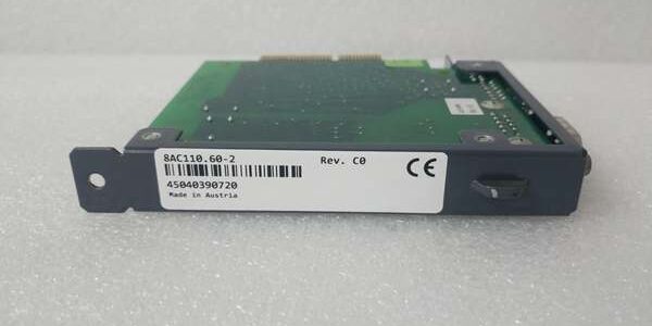
Product Core Brief
- Model: X20AIB744
- Brand: B&R Industrial Automation
- Series: X20 Modular Distributed I/O Platform
- Core Function: Digitizes differential mV/V signals from 4-wire full-bridge strain gauge load cells for weighing, force and tension closed-loop measurement
- Product Type: Analog Input I/O Slice Module
- Key Specs: 4 independent full-bridge channels | 24-bit sigma-delta ADC | 5.5V/65mA per-channel sensor excitation | Built-in open-wire fault diagnostics
- Note: New Original inventory; X20BB base terminal blocks sold separately
Key Technical Specifications
- Channel Count: 4 isolated full-bridge strain gauge differential input channels
- Input Signal Range: 2–256 mV/V differential bridge output
- ADC Architecture: 24-bit sigma-delta conversion; valid digital range -8,388,607 to 8,388,607
- Sensor Excitation: 5.5 VDC regulated supply, max 65 mA per channel, short-circuit protected
- Input Filter: 3rd-order 60dB roll-off anti-aliasing filter, 2.5 kHz cutoff frequency
- Galvanic Isolation: 500 Vₑff isolation between analog input circuitry and X2X backplane bus
- Onboard Diagnostics: Per-channel open-circuit wire detection, broken bridge supply monitoring, module RUN/ERROR LED indicators
- Power Dissipation: 0.01 W bus power draw; 1 W internal I/O base load; +1.43 W resistive actuator additional loss
- Mechanical: 12.5 mm single-width DIN rail slice; vertical/horizontal mounting compatible; IP20 cabinet-only protection
- Environmental Ratings: Horizontal mount -25°C to +60°C; vertical mount -25°C to +50°C; storage -40°C to +85°C
- Firmware ID Code: 0xE286
- Certifications: CE, UL cULus, EAC, RoHS industrial compliance
Product Introduction
This narrow I/O slice delivers high-resolution weight and force data for batching presses, material tension control, and filling machine weighing stations. Each channel supplies regulated bridge excitation and differential signal capture without external signal amplifiers.
The integrated fault detection flags broken load cell wiring at the backplane bus level, while galvanic isolation eliminates ground loop measurement drift common on multi-sensor weighing racks. It connects directly via X2X Link to compatible CPU controllers for real-time recipe weight calculation.
QA & Testing SOP (Transparency Building)
- Incoming Inspection: Cross-reference OEM serial database to validate genuine hardware; inspect terminal spring contacts for deformation, module locking latches for cracking, and PCB edge connectors for bent pins.
- Live Testing: Mount the slice to matching X20BB base block; supply stabilized 24VDC from a Fluke 115 power supply; feed calibrated mV/V reference signals to all four channels for 24-hour continuous sampling, logging ADC linearity and fault detection response hourly.
- Electrical Testing: 500V Megger insulation test between analog input terminals and X2X backplane ground; pass threshold set to >10MΩ isolation resistance.
- Firmware/Config Backup: Record hardware revision code and default channel filter parameters via Automation Studio; photograph terminal wiring pinout layout for replacement matching.
- Final QC & Packaging: Wipe housing with ESD-safe isopropyl alcohol; seal in conductive anti-static shielding bag; attach printed test tag with serial trace and 24-hour measurement linearity pass metrics.
Installation Pitfalls & Guide (Engineer to Engineer)
❗ Unmatched 4-Wire Load Cell Wiring: Using 3-wire strain gauge sensors disables internal cable length compensation and introduces consistent weight offset errors across all batches.❗ High-Current Cable Parallel Routing: Running AC power cabling alongside load cell signal wiring distorts mV/V differential signals, creating ±12 count ADC noise that ruins weighing precision.❗ Underrated Excitation Loads: Paralleling multiple low-impedance bridge sensors on one channel exceeds the 65 mA 5.5V supply limit, triggering overcurrent protection and intermittent measurement dropouts.❗ Missing X2X Bus Termination Plate: The last slice on an X2X rack chain requires X20AC0SR1 end cap; omitted termination generates bus sampling jitter that destabilizes high-speed weighing control loops.❗ Unmitigated ESD Exposure: Low-humidity static discharges damage sensitive 24-bit ADC front-end circuitry; wear grounded anti-static wristbands before plugging the slice onto the backplane base block.
4-Step Replacement Guide
- Pre-install: Full rack power down; photograph existing slice terminal wiring, channel sensor assignments, and X2X bus end cap placement for exact configuration replication.
- Removal: Depress orange locking latch; slide the slice upward off the X20BB base block; disconnect all load cell field wiring terminals.
- Install: Seat the new unit flush onto the empty base block until the latch clicks fully; reattach all strain gauge wiring matching photographed pin assignments.
- Power-on Test: Restore 24VDC rack supply; verify steady module RUN LED, run channel open-wire fault test, and validate calibrated weight reading consistency before production batch runs.
FAQ (Frequently Asked Questions)
Q: Can this slice operate with half-bridge or quarter-bridge strain gauge sensors?A: No. Hardware circuitry is hard-configured exclusively for full-bridge 4-wire load cell inputs. Half/quarter bridge setups require external signal amplifiers to match the mV/V input range.Q: Does the module support hot-swapping while the X20 rack remains powered?A: No. Removing the slice live breaks the X2X synchronous bus, halts all distributed I/O sampling, and risks permanent damage to the backplane bus transceiver chips. Full rack power shutdown is mandatory.Q: What maximum cable length works reliably between the slice and load cells?A: Up to 30 meters with shielded twisted-pair B&R weighing cable; unshielded generic cabling introduces measurable signal noise beyond 10 meters of run length.Q: Can multiple slices share a single X2X bus chain with motion control I/O modules?A: Yes, the device shares the standard X2X Link protocol with digital I/O and counter slices; maintain separate cable trays for weighing analog wiring to avoid motion drive EMI interference.Q: How does the open-circuit diagnostic function report faults to the controller?A: A dedicated status bit sets in the module process image register, paired with a red channel LED indicator for fast on-site troubleshooting without software access.Q: Are third-party strain gauge sensors fully compatible with the 5.5V excitation supply?A: Most standard industrial load cells operate within the 2–256 mV/V range, but low-sensitivity miniature sensors below 2 mV/V full scale produce ADC resolution limitations in weight calculation routines.Q: What warranty coverage applies to surplus stock of the slice?A: Standard 12-month functional warranty covers ADC, excitation supply and diagnostic circuit manufacturing defects; damage from ESD mishandling, overloaded bridge channels, or unshielded wiring-induced signal failure is fully excluded from coverage.




