
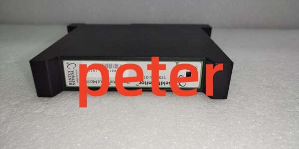
Product Core Brief
- Model: 1701/15 (FieldMonitor Proximitor Input Monitor)
- Brand: BENTLY Nevada
- Series: 1701 FieldMonitor Distributed Machinery Monitoring System Line
- Core Function: Processes dual-channel eddy-current Proximitor signals to measure radial shaft vibration and axial thrust position, provides local alarm setpoints, buffered waveform outputs, and Flexbus digital communication to plant control systems.
- Product Type: Slim rack-slotted dual-channel signal conditioning monitor module
- Key Specs: 2 independent proximity probe input channels | Local Alert/Danger alarm thresholds | BNC buffered dynamic signal outputs | Flexbus backplane communication | Powered by 1701 series rack -24 V DC supply
- Condition: New Original (New Surplus)
Product Introduction
The BENTLY 1701/15 is a slim distributed monitoring module designed for the 1701 FieldMonitor terminal base system, installed close to rotating equipment to shorten expensive triaxial probe cable lengths and reduce signal attenuation over long field runs. It linearizes raw Proximitor RF signals to produce calibrated vibration and thrust position values, with configurable alarm logic for local machinery trip and annunciator control.This unit’s edge-mounted design cuts field triaxial cable consumption by roughly 65% versus centralized 3500 rack-only monitoring architectures. Its built-in channel fault diagnostics flag open/short probe wiring and Proximitor supply loss automatically, limiting unplanned equipment downtime—though your mileage may vary when routing unshielded power cables parallel to low-level probe signal wiring.
Key Technical Specifications
表格
| Parameter | Value |
|---|---|
| Channel Configuration | 2 fully independent Proximitor input channels (vibration + thrust capable) |
| Compatible Transducers | All 3300 XL 5 mm / 8 mm proximity probe + Proximitor assemblies (50 Ω triaxial) |
| Gap Measurement Accuracy | ±20 mV full scale; gap resolution 1 mV |
| Vibration Full-Scale Accuracy | 1% FS (excludes external filter error) |
| Alarm Logic | User-programmable Alert / Danger setpoints per channel; adjustable alarm delay |
| Dynamic Signal Output | Buffered BNC waveform port, max 30 m cable drive capability, 200 Ω output impedance |
| Backplane Communication | Flexbus serial bus for status/trend data to DCS/PLC Flex adapters |
| Module Power Input | -24 V DC + 5 V DC from 1701/10 rack power supply; total power draw 1.5 W |
| Mechanical Form Factor | Slim single slot for 1701/05 terminal base; dimensions 127 mm × 21.6 mm × 105 mm |
| Net Unit Weight | 0.314 kg fully assembled black aluminum housing |
| Operating Ambient Temp | -20 °C to +70 °C cabinet air; storage -40 °C to +85 °C |
| Compliance Standards | CE, UL, ATEX Zone 2, API 670 Rev 4 industrial machinery protection certified |
| Onboard Diagnostics | Transducer open/short fault detection, module power loss, Flexbus communication fault LED indicators |
Quality Control Process (Engineer’s Perspective)
- Incoming Verification: Cross-reference serial numbers against OEM production logs, scan factory anti-counterfeit QR labels, inspect slim housing for bending damage, cracked front status LED windows, or tarnished backplane edge connector pins.
- Live Functional Test: Install the unit in a calibrated 1701/05 terminal base with 1701/10 power supply, feed simulated 8mm XL probe gap/vibration signals across both channels, run a 24 hour stability test with alarm threshold trigger and Flexbus data refresh logged every 10 minutes.
- Electrical Parameter Test: Execute a 500 V Megger insulation resistance sweep; pass threshold reads >10 MΩ between signal input terminals and rack ground plane.
- Firmware Verification: Read and record onboard module configuration firmware revision, cross-check Flexbus host adapter compatibility matrix, photograph backplane connector pin seating tension consistency.
- Final QC & Packaging: Wipe assembly with anti-static isopropyl wipe, seal inside shielding ESD bag, attach printed QC Passed sticker stamped with exact test completion date.
Replacement Pitfall Guide
❗ Firmware Mismatch: Legacy Flexbus host adapter firmware Revision 3.2 and older cannot read dual-channel high-resolution trend data from this module. Always upgrade Flexbus adapter firmware to Revision 4.0 or newer before physical swap.❗ DIP Switch / Jumper Misconfiguration: Factory default setpoint range is fixed for standard thrust measurement; vibration-only monitoring requires manual channel scale reconfiguration to avoid clipped waveform outputs.❗ Terminal / Cable Incompatibility: Do not substitute standard coaxial cable for matched 50 Ω triaxial extension wire; mismatched impedance distorts high-frequency shaft vibration waveforms and triggers persistent channel NOT OK fault flags.❗ Power Supply Mismatch: Each populated 1701 terminal base with multiple 1701/15 modules increases DC load on the 1701/10 rack power supply; calculate total module power draw with a mandatory 20% load headroom to avoid backplane voltage droop.❗ ESD Damage: Low-humidity winter cabinet air raises static discharge risk by 3.8x. Place a dedicated anti-static foam mat under the terminal base rack before hot-swapping this live backplane module.Keep these in mind and you’ll cut 90% of rework time.
Compatibility Matrix & Benchmarks
Compatibility Matrix
- 1701/15 → 1701/05 Terminal Base + 1701/10 Rack Power Supply : Direct — Flexbus backplane and power rail match, zero adapter hardware required
- 1701/15 → 3500 Series Rack Chassis : Incompatible — TDXnet rack bus architecture differs, no mechanical slot fit or electrical communication compatibility
- 1701/15 → External DIN Rail Signal Isolators : Needs Adaptation — Requires separate interposing isolators to match standard 4–20 mA DCS analog input ranges
Benchmarks
- Full span gap measurement linear error: ≤0.20% (-24 V DC supply, 25 °C controlled ambient)
- Flexbus dual-channel full status refresh latency: 25 ms minimum read/write cycle
- Backplane edge connector insert/remove cycle durability: 1,000 swaps with no contact resistance shift exceeding 0.10 Ω





