Product Core Brief
- Model: D20C Termination
- Brand: GE Energy / GE Intelligent Platforms
- Series: GE D20 / D200 RTU Family
- Core Function: Control output termination board for the GE D20/D200 RTU, providing field wiring interface for relay or control outputs.
- Product Type: RTU I/O Termination Board
- Condition: New Original / New Surplus (subject to available stock)
Key Technical Specifications
- Part Number: D20C Termination (commonly referenced as D20C board, e.g. 820-0387 in D200 RTU documentation)
- Platform: GE D20 / D200 Remote Terminal Unit (RTU)
- Function: Control output termination / relay output termination board
- Board Type: D20C termination board for D200 RTU I/O modules
- Interface: Screw-terminal or connector-based field wiring interface for control outputs
- Mounting: Installed in the D20/D200 I/O assembly or termination panel
- Typical Application: Substation automation, SCADA RTU control outputs, breaker/trip relay interfacing, and status signaling
Product Introduction (No Fluff)
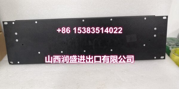
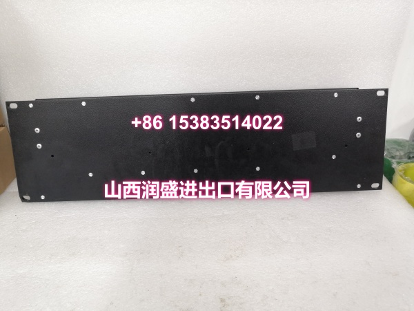
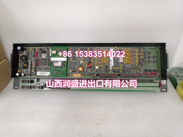
The D20C Termination is a control output termination board used with the GE D20/D200 RTU platform. In D200 RTU documentation, the D20C board is described as part of the I/O module connection structure, providing the field termination interface for control or relay outputs.
This board does not act as a processor or communication module. Instead, it serves as the wiring interface between the RTU output circuitry and external devices such as trip relays, alarm relays, breaker control circuits, and signaling equipment. By consolidating output wiring on a dedicated termination board, it simplifies installation, maintenance, and troubleshooting in substation and SCADA applications.
The D20C termination board is typically used together with D20/D200 I/O modules and associated backplane or chassis hardware. When replacing or commissioning this board, field wiring, output polarity, and relay assignments should be verified against the existing RTU configuration and site drawings.
QA & Testing SOP (Dynamic & Transparent)
Each surplus unit undergoes:
- Part Number Verification: Confirm the label or board marking identifies the D20C termination board.
- Visual Inspection: Inspect terminal blocks, connectors, PCB surface, and mounting hardware for corrosion, burns, or physical damage.
- Terminal Check: Verify screw terminals or connector pins are intact, clean, and free of oxidation.
- Mechanical Fit Check: Confirm the board mounts correctly in the applicable D20/D200 I/O or termination assembly.
- Wiring Integrity Check: Inspect for loose terminals, cracked solder joints, or damaged traces.
- Continuity Check: Where possible, verify continuity between terminal points and associated I/O interfaces.
- Output Interface Check: Confirm the board aligns with the expected control output configuration for the installed RTU.
- Packaging: Pack in anti-static bags with foam cushioning. Protect terminal blocks and connector interfaces during transit.
Installation Pitfalls & Guide (Engineer to Engineer)
Confirm it is the correct termination board. D20/D200 RTUs use multiple I/O and termination boards. Verify that D20C is the correct control output termination for your chassis and I/O configuration.
Check field wiring before energizing. Incorrect wiring on control output terminals can energize trip circuits or relay outputs unintentionally. Verify wiring against site drawings.
Do not mix incompatible I/O boards. The D20C termination board must match the associated I/O module and RTU configuration. Substituting unrelated termination boards may cause wiring or functional mismatches.
Verify output assignments. Control outputs may be mapped to breaker tripping, alarm signaling, or interlock functions. Confirm point assignments in ConfigPro or the RTU database before commissioning.
Label all terminals. Field wiring should be clearly labeled to avoid confusion during maintenance or replacement.
Document changes. Record slot position, terminal assignments, and any replaced components. This is critical for future troubleshooting.
Installation Steps:
- Pre-install: Confirm part number D20C Termination and compatibility with the installed D20/D200 RTU.
- Isolate Power: De-energize the RTU and isolate control output circuits before working on termination wiring.
- Remove Old Board: Disconnect field wiring carefully and remove the existing termination board.
- Install New Board: Mount the D20C termination board and verify mechanical engagement.
- Reconnect Wiring: Reconnect field wiring according to the original terminal assignments.
- Commission: Power up the RTU. Verify output status, relay behavior, and control point mapping.
Technical FAQ
1. What is the D20C Termination? It is a control output termination board for the GE D20/D200 RTU, providing the field wiring interface for relay or control outputs.
2. Is it a processor or communication module? No. It is an I/O termination board. Processor and communication functions are handled by separate D20/D200 modules.
3. What is it used for? It is typically used to terminate control outputs such as trip relays, alarm relays, breaker control signals, and other SCADA output circuits.
4. Can it be used on any D20 RTU? It is intended for D20/D200 RTU configurations that use the D20C termination board. Compatibility should be confirmed against the specific RTU model and I/O assembly.
5. What software is used to configure the related outputs? D20/D200 RTU I/O and control points are typically configured using ConfigPro or equivalent RTU configuration tools.
6. What warranty do you offer on surplus stock? Terms vary by condition and availability. For surplus industrial modules, we typically provide a short functional guarantee. Confirm details at time of order.