Product Core Brief
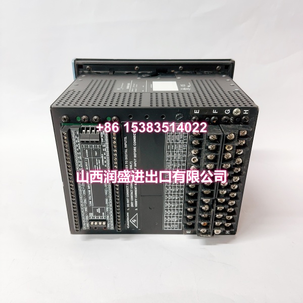
- Model: 760-P5-G5-S5-HI-A20-R-E
- Brand: GE Multilin
- Series: SR760 Feeder Management Relay
- Core Function: Digital feeder protection and management relay with auto-reclose, metering, event recording, waveform capture, and configurable I/O.
- Product Type: Feeder Management Relay (SR760 platform)
- Condition: New Original / New Surplus (subject to available stock)
Key Technical Specifications
- Order Code Breakdown:
- 760: SR760 Feeder Management Relay with auto-reclose function
- P5: 5 A phase current inputs
- G5: 5 A zero-sequence (ground) current input
- S5: 5 A sensitive ground current input
- HI: Control power 88–300 VAC (48–62 Hz) or 70–265 VDC
- A20: Eight (8) analog outputs, 4–20 mA
- R: Red breaker-closed LED indicator
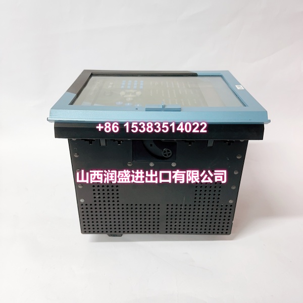
- E: Enhanced display (wider LCD, streamlined keypad)
- Platform: GE Multilin SR760 / SR Family
- Current Rating: All current inputs at 5 A (phase, zero-sequence, sensitive ground)
- Control Power: High-voltage AC/DC supply (HI option)
- Analog Outputs: 8 × 4–20 mA
- Display: 40-character alphanumeric LCD (enhanced version)
- Communication: RS232 port for EnerVista software; optional 10 Mbps Ethernet available
- Protection Functions: Phase/ground overcurrent, directional overcurrent, sensitive ground, negative sequence, undervoltage/overvoltage, under/overfrequency, reverse power, synchrocheck, breaker failure, 4-shot auto-reclose
- Metering & Diagnostics: Event reports, waveform capture, data logger, IRIG-B time sync
- Construction: Draw-out case for reduced downtime during maintenance; optional conformal coating for harsh environments
- Protocols: DNP 3.0, Modbus (optional Ethernet on some variants)
Product Introduction (No Fluff)
The GE Multilin 760-P5-G5-S5-HI-A20-R-E is an SR760 Feeder Management Relay designed for primary protection and control of distribution feeders. This specific configuration uses 5 A rated inputs across all current channels (phase, zero-sequence, and sensitive ground), making it suitable for systems with 5 A CT secondaries.
The relay provides comprehensive protection including directional phase/ground overcurrent, sensitive ground, negative sequence, voltage and frequency elements, reverse power, synchrocheck, and a 4-shot auto-reclose function unique to the 760 series. Eight 4–20 mA analog outputs support real-time metering integration, and the enhanced display (E suffix) offers a wider LCD with a streamlined keypad layout for improved local interaction.
Configuration is performed via the front-panel keypad/LCD or through GE Multilin’s EnerVista software via the RS232 port. The draw-out construction allows relay replacement without disconnecting field wiring, minimizing downtime during maintenance.
Note: GE Vernova has discontinued manufacturing of the 750/760 series. The recommended replacement platform is the GE 850 feeder protection relay.
QA & Testing SOP (Dynamic & Transparent)
Feeder management relays are critical protection devices. Each surplus unit undergoes:
- Order Code Verification: Confirm the nameplate reads 760-P5-G5-S5-HI-A20-R-E exactly. Verify P5/G5/S5 (all 5 A inputs), HI supply, A20 outputs, and E display suffix.
- Visual Inspection: Inspect the draw-out connector pins, terminal blocks, front-panel LCD, keypad, and LED indicators for corrosion, bent pins, or physical damage.
- Power-Up Test: Apply HI-rated control power (88–300 VAC or 70–265 VDC). Confirm the relay boots without fault alarms.
- Display & Keypad Check: Verify the enhanced LCD displays correctly. Test keypad navigation through setpoints, actual values, and target displays.
- Analog Output Test: Verify all eight 4–20 mA outputs produce correct current levels across the range.
- Protection Function Test: Inject test currents to verify phase overcurrent, ground overcurrent, and sensitive ground pickup/trip operations. Confirm auto-reclose sequencing if required.
- Communication Test: Connect via RS232 to EnerVista software. Verify read/write access to setpoints and event records.
- Packaging: Pack in anti-static bags with foam cushioning. Protect the draw-out connector and front panel during transit.
Installation Pitfalls & Guide (Engineer to Engineer)
Verify CT secondary ratings before installation. This unit is configured for 5 A CT secondaries on all current inputs (P5/G5/S5). Connecting it to a 1 A CT secondary will result in incorrect metering and protection operation.
Confirm control power supply matches the HI rating. The HI option requires 88–300 VAC (48–62 Hz) or 70–265 VDC. Applying LO-rated voltage (20–48 VAC / 25–60 VDC) may cause the relay to fail to power up.
Set auto-reclose parameters carefully. The 760 supports up to 4 reclose shots. Incorrect reclose timing or shot count can cause unnecessary stress on the distribution system.
Check draw-out connector engagement. The relay must be fully seated in its chassis. A partially engaged connector causes intermittent communication or I/O failures.
Verify analog output scaling. The eight 4–20 mA outputs are user-configurable. Confirm scaling matches the connected SCADA or metering system expectations.
Back up settings before replacement. Export the full setpoint file via EnerVista before swapping units. Import into the replacement relay to minimize commissioning time.
Note the product discontinuation. The 750/760 series is discontinued. For new installations or long-term strategy, consider migrating to the GE 850 platform.
Replacement Steps:
- Pre-install: Confirm order code 760-P5-G5-S5-HI-A20-R-E. Export setpoints from the existing relay via EnerVista. Prepare LOTO.
- Removal: Isolate control power. Use the draw-out mechanism to remove the relay without disconnecting field wiring.
- Install: Insert the replacement relay into the chassis. Verify full connector engagement. Apply control power.
- Commissioning: Import setpoints. Verify display, LED status, analog outputs, and communication. Perform secondary injection testing on protection elements before returning to service.
Technical FAQ
1. What does the “760” designation mean versus “750”? The SR760 includes a 4-shot auto-reclose function that the SR750 does not have. Both are feeder management relays in the same SR Family platform.
2. What does the “E” suffix indicate? The “E” suffix denotes the enhanced display version with a wider LCD and streamlined keypad layout compared to the base relay.
3. Can I substitute a P1/G1/S1 unit for this P5/G5/S5 unit? No. P1/G1/S1 units use 1 A CT secondaries, while this unit is configured for 5 A on all current inputs. Substituting without changing CTs will cause incorrect protection operation.
4. What is the HI control power option? HI indicates high-voltage control power: 88–300 VAC (48–62 Hz) or 70–265 VDC. The alternative LO option accepts 20–48 VAC or 25–60 VDC.
5. Is this relay still in production? No. GE Vernova has discontinued the 750/760 series. The recommended replacement is the GE 850 feeder protection relay.
6. What warranty do you offer on surplus stock? Terms vary by condition and availability. For surplus industrial relays, we typically provide a short functional guarantee. Confirm details at time of order.