Product Core Brief
- Model: 531X309SPCAJG1
- Brand: GE / GE Industrial Systems
- Series: GE Speedtronic Mark VI / 531X Drive & Exciter Replacement Family
- Core Function: SPCA terminal board for field I/O termination and signal routing within GE drive and turbine control systems.
- Product Type: SPCA Terminal Board
- Associated Assembly Family: F31X309SPCA
- Condition: New Original / New Surplus (subject to available stock)
Key Technical Specifications
- Part Number: 531X309SPCAJG1
- Product Type: SPCA Terminal Board
- Platform: GE Speedtronic Mark VI / 531X drive and exciter replacement series
- Associated Family: F31X309SPCA
- Interconnect: Ribbon-cable connection to paired control/driver board
- Mounting: Installed within GE 531X / Mark VI control pack chassis or drive cabinet
- Status Indicators: LED indicators for board operation and fault monitoring
- Configuration Software: ToolboxST / Mark VI configuration tools
- Operating Temperature: Industrial range, typically 0 to 60 °C, cabinet-mounted, non-condensing
- Power: Draws low-level board power from host assembly; no external supply required
- Application: GE drive control, exciter systems, and turbine control I/O termination
Product Introduction (No Fluff)
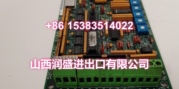
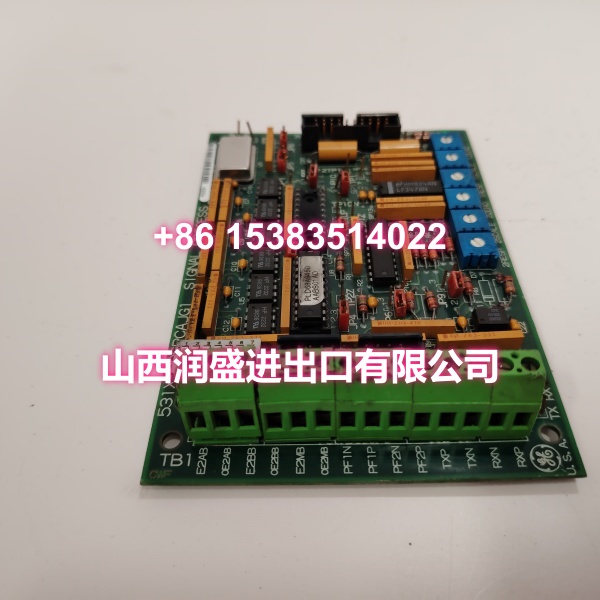
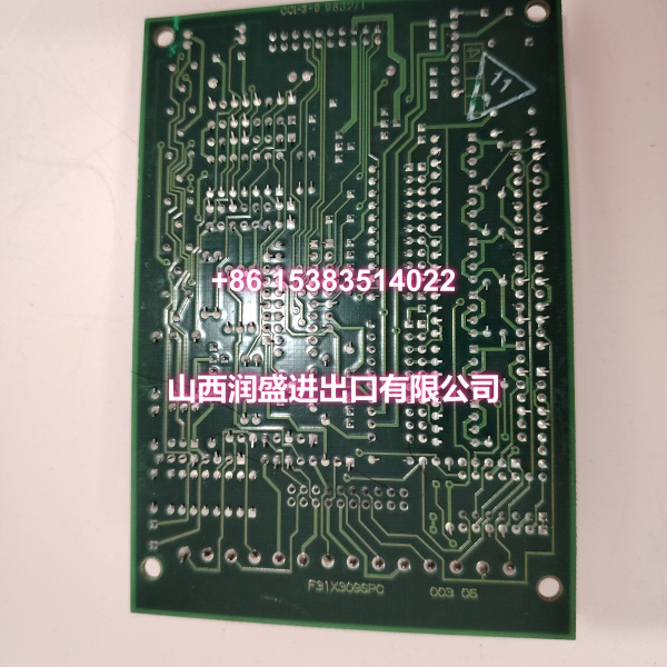
The GE 531X309SPCAJG1 is an SPCA terminal board used in GE Speedtronic Mark VI and 531X drive/exciter replacement platforms. Part of the F31X309SPCA family, this board serves as a field wiring and signal interface element within the GE control architecture.
The SPCA board consolidates field I/O termination and signal routing onto a single terminal board, connecting to its paired control or driver board via ribbon cable. It provides organized screw-terminal access for field wiring, onboard LED indicators for operational monitoring, and industrial-grade components designed for harsh electrical noise environments common in drive and turbine control cabinets.
For plant engineers maintaining GE drive skids or legacy Mark VI systems, the SPCA board simplifies troubleshooting by bringing all field wiring to labeled terminal points. The “J” suffix indicates a specific hardware revision within the 531X309SPCA family, and the “G1” revision denotes incremental refinements for compatibility and stability within the 531X line.
QA & Testing SOP (Dynamic & Transparent)
Terminal boards are the first point of contact for field signals. Each surplus unit undergoes:
- Part Number Verification: Confirm the board label reads 531X309SPCAJG1 exactly. Check for F31X309SPCA family markings.
- Visual Inspection: Inspect terminal blocks, ribbon cable connectors, LED indicators, and solder joints for corrosion, burnt traces, or cracked connections.
- Connector Integrity Check: Verify all ribbon cable connectors and terminal blocks are secure and free of bent pins or oxidation.
- Power-Up Test: Apply appropriate control power in a test chassis. Confirm the board boots without fault LEDs or watchdog errors.
- Signal Path Verification: Test signal routing paths where possible. Verify the board properly passes field signals to the paired control board.
- Packaging: Pack in anti-static bags with foam cushioning and rigid outer packaging to protect connectors during transit.
Installation Pitfalls & Guide (Engineer to Engineer)
Verify the exact suffix before swapping. The 531X309SPCA family includes SPCAFG1, SPCAGG1, SPCAHG1, SPCAJG1, and others. Suffix differences can indicate hardware revisions or I/O configuration changes that may not be directly interchangeable.
Confirm ribbon cable orientation. The SPCA connects to its paired control/driver board via ribbon cable. Reversed or loose ribbon connections cause signal loss or incorrect I/O readings.
Document terminal wiring before removal. Record all terminal wiring assignments and LED states from the old board to speed up commissioning of the replacement.
Check for associated board compatibility. The SPCA board is designed to work with specific control/driver boards within the 531X family. Verify the paired board model before installation.
Handle terminal blocks with care. The screw-terminal blocks are susceptible to damage during wiring. Avoid over-tightening and ensure proper wire gauge.
Replacement Steps:
- Pre-install: Confirm part number 531X309SPCAJG1, document existing wiring settings, and prepare LOTO.
- Removal: Power down the control cabinet. Label all field wiring. Disconnect ribbon cable and terminal wiring. Remove the old board.
- Install: Seat the new board. Reconnect ribbon cable and field wiring per documented assignments.
- Commissioning: Apply power. Verify LED status indicators. Test signal paths and confirm proper operation before returning to service.
Technical FAQ
1. What system is the 531X309SPCAJG1 used in? It is an SPCA terminal board used in GE Speedtronic Mark VI and 531X drive/exciter replacement platforms, installed inside GE drive and turbine control cabinets.
2. What does “SPCA” mean? SPCA refers to the terminal board function within the 531X family. It consolidates field I/O wiring and signal routing onto a single board for organized field termination.
3. What is the difference between SPCAJG1, SPCAFG1, SPCAGG1, and SPCAHG1? These are suffix variants within the 531X309SPCA family. The suffix letters indicate hardware revisions or I/O configuration differences. Interchangeability must be confirmed against your system manual or GE technical support.
4. Can this board be used with Mark VIe systems? Mark VI and Mark VIe are related but distinct platforms. While they share some 531X hardware families, compatibility depends on the specific I/O pack and firmware. Verify against your system documentation before cross-platform substitution.
5. What warranty do you offer on surplus stock? Terms vary by condition and availability. For surplus industrial boards, we typically provide a short functional guarantee. Confirm details at time of order.