Product Core Brief
- Model: 369-HI-0-0-0-0
- Brand: GE Multilin
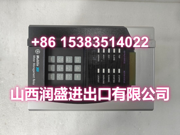
- Series: Multilin 369 Motor Management Relay
- Core Function: Digital protection, control, and monitoring for three-phase AC motors using adaptive thermal modeling and CT-based current sensing.
- Product Type: Motor Management Relay
- Key Specs: HI control power 50–300 VDC / 40–265 VAC | No RTD option | No metering option | RS-485 Modbus RTU
- Condition: New Original / New Surplus (subject to available stock)
Key Technical Specifications
- Part Number: 369-HI-0-0-0-0
- Product Type: Digital Motor Management Relay
- Control Power (HI): 50–300 VDC / 40–265 VAC, 50/60 Hz
- Power Consumption: Nominal 20 VA, Max 65 VA
- Phase Current Input: Via external CTs, 1 A or 5 A secondary
- Ground Fault Input: Dedicated ground CT input
- RTD Inputs: None (0 option = no RTD module)
- Metering Option: None (0 option = no voltage/metering package)
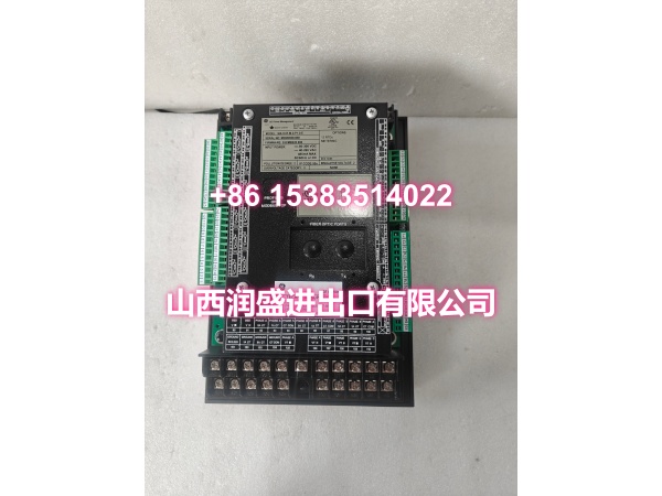
- Communication: RS-485 (Modbus RTU), front-panel RS-232
- Display: 40-character alphanumeric LCD with status LEDs
- Operating Temperature: -40°C to +60°C
- Enclosure Rating: IP50, panel/door mount
- Configuration Software: EnerVista 369
Product Introduction (No Fluff)
The GE Multilin 369-HI-0-0-0-0 is a digital motor management relay built to protect and monitor three-phase AC motors in industrial process environments. It uses an adaptive thermal model that “learns” motor characteristics during startup—capturing acceleration time, inrush current, and cooling behavior—to differentiate between a legitimate start and a mechanical jam or stall.
This specific configuration carries the HI power supply option but omits RTD inputs and the metering package. That makes it a solid fit for applications where you need dependable overcurrent, ground fault, phase unbalance, and thermal overload protection without the added cost of temperature monitoring or voltage metering. The built-in RS-485 Modbus RTU interface plugs straight into most existing SCADA or PLC architectures without requiring extra communication cards.
QA & Testing SOP (Dynamic & Transparent)
Surplus motor protection relays need more than a visual check. Here is how we verify this unit before it ships:
- Part Number & Firmware Verification: Confirm the full model code reads 369-HI-0-0-0-0 on the rear label. Power up and log the firmware revision from the front-panel menu to ensure it matches the expected build.
- Self-Test & Internal Diagnostics: Run the relay’s built-in self-test sequence. Check for any stored self-test errors, watchdog faults, or EEPROM warnings that would indicate internal degradation.
- Control Power Burn-In: Apply HI-range control power (within 50–300 VDC or 40–265 VAC) and let the unit stabilize. Verify the display boots cleanly and all status LEDs illuminate correctly.
- CT Input Simulation: Inject a known secondary current through the phase CT inputs using a calibrated test set. Confirm the relay reads current accurately and that the trip/alarm relay outputs respond to programmed thresholds.
- Communication & Packaging: Test RS-485 Modbus RTU communication with a laptop or test rack. Verify register reads match displayed values. Pack in anti-static bags with foam cushioning for transit.
Installation Pitfalls & Guide (Engineer to Engineer)
❗ This unit has NO RTD inputs. If your motor relies on stator or bearing temperature monitoring, this configuration will not support it. Verify your protection strategy before installation.
❗ No metering package means no voltage inputs. You will not get kW, kVAR, power factor, or voltage readings from this relay. If your SCADA screen expects those values, you will need a separate meter or a different 369 configuration.
❗ CT polarity matters. Reversed CT wiring on any phase will cause incorrect current unbalance readings and can trigger false trips. Double-check polarity marks before tightening terminals.
❗ Ground the filter terminal. The 369 requires both safety ground and filter ground connected to the main ground bus. Skipping the filter ground can cause communication noise and erratic behavior on the RS-485 link.
Replacement Steps:
- Pre-install: Verify the model code, back up existing settings from the old relay via EnerVista 369, and prepare LOTO.
- Removal: Label all CT, DI/DO, and communication wires. Remove terminal blocks and unmount the relay.
- Install: Mount the new unit, reconnect wiring per the label diagram, and verify CT polarity and ground connections.
- Power-on Test: Apply control power, load the saved settings, inject test current, and confirm trip/alarm outputs before returning the motor to service.
Technical FAQ
1. What is the difference between 369-HI-0-0-0-0 and 369-HI-R-M-0-0-0-0? The “R” adds 12 built-in RTD inputs for stator/bearing temperature monitoring. The “M” adds the metering package with voltage inputs for kW, kVAR, PF, and energy readings. Your unit has neither—so it is current-only protection with Modbus communication.
2. Can I add RTD or metering options in the field? No. GE Multilin requires these options to be factory-installed. Field hardware modifications void the warranty. If you need RTDs or metering later, you would need a different model or an external module.
3. Is the 369 series still in production? Manufacturing of the 369 series has been discontinued by GE Vernova. The recommended replacement platform is the GE Multilin 859. Surplus 369 units remain a practical option for like-for-like replacements where re-engineering is not feasible.
4. What warranty do you offer on surplus stock? Terms vary by condition and availability. For surplus industrial relays, we typically provide a short functional guarantee. Confirm details at time of order.
5. Can this relay integrate with my existing PLC? Yes. The built-in RS-485 port supports Modbus RTU, which is compatible with most PLCs and SCADA systems. You will need to map the relay’s holding registers to your PLC tags. No optional Ethernet card is present in this configuration.