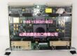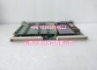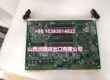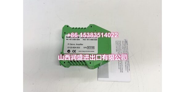
Product Quick-Glance Brief
- Model: MOOG G122-829-001
- OEM: MOOG
- Category: Analog P-I Servo Amplifier
- Core Function: Provides configurable proportional-integral control for hydraulic servo valves with integrated diagnostics.
- Key Specs: 24 VDC Supply, ±10 V Analog I/O, DIN-Rail Mount
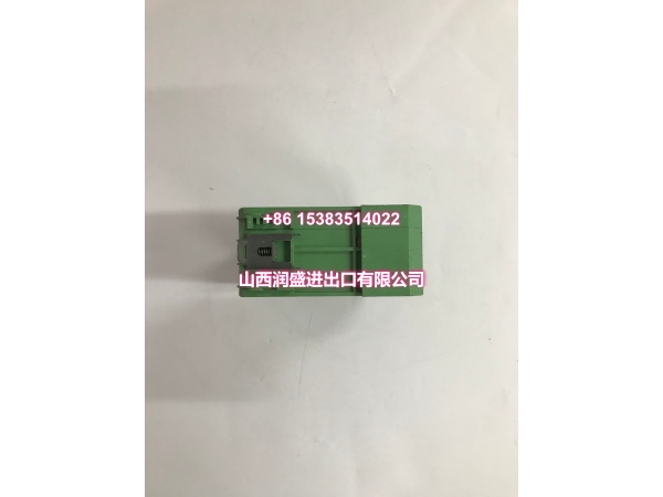
Technical Overview & Field Application
Tuning a hydraulic loop shouldn’t require a PhD in analog circuits. The MOOG simplifies this by putting P-I control in a single, user-configurable module. Internal DIP switches let you select proportional, integral, or combined modes without swapping hardware. One amplifier covers multiple application types.
This unit accepts standard ±10 V or 4-20 mA command signals and drives two-coil servo valves with bipolar current output. Front-panel potentiometers let you adjust gain, bias, and feedback directly at the cabinet. No laptop. No proprietary software. Just a screwdriver and a multimeter.
Field engineers value the built-in diagnostics. LED indicators show enable status, fault conditions, and output levels. Test points on the front panel let you monitor internal signals without breaking out oscilloscope probes. When a press or test rig goes down at 2 AM, that accessibility saves hours of troubleshooting.
Essential Specifications
| Parameter | Specification |
|---|---|
| Supply Voltage | 24 VDC Nominal (18–30 VDC) |
| Control Mode | P, I, or P-I (Switch Selectable) |
| Command Input | ±10 V / 4–20 mA (Single-Ended) |
| Feedback Input | ±10 V / 4–20 mA (Differential) |
| Output Type | Bipolar Current (±40 mA / ±60 mA) |
| Output Load | Max 500 Ω (Current Mode) |
| Mounting | DIN-Rail (EN 60715) |
| Operating Temp | 0 to +50 °C |
| Diagnostics | LED Status + Front Panel Test Points |
| EMC | CE Compliant (Shielded Wiring Required) |
Quality Assurance Protocol
Every MOOG is validated to ensure analog precision and reliability. We don’t ship amplifiers that “mostly” work.
- P-I Mode Verification: We test all three switch configurations (P-only, I-only, P-I) to confirm internal switching logic and control response.
- Gain Linearity Sweep: Command inputs are swept across ±10 V range. Output current must track within ±1% linearity.
- Feedback Path Check: Differential feedback inputs are validated for common-mode rejection and zero-offset accuracy.
- Thermal Stability Test: Units run at full output for 2 hours at 50 °C ambient. Gain drift >2% triggers rejection.
Note: Amplifiers showing output ripple >50 mV during testing are quarantined. Excessive ripple causes servo valve chatter and premature wear.
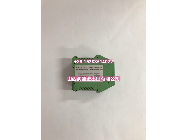
Engineer’s Installation / Replacement Notes
Set P-I switches BEFORE powering up. Changing switch positions while energized can cause output spikes that damage the servo valve torque motor. Always de-energize, adjust, then re-apply power.
- Shield Grounding is Critical: The ±10 V analog signals are susceptible to EMI. Use shielded cable and ground the shield at the controller end only. Grounding at both ends creates loops that look like command noise.
- Ventilation Clearance: The DIN-rail housing relies on natural convection. Maintain 50 mm clearance above and below the module. Blocking vents causes thermal drift and premature failure.
- Feedback Wiring: Keep feedback cables separate from power and output lines. Route them through separate cable glands. Induced noise on the feedback path causes oscillation that no amount of gain tuning will fix.
- Zero Adjustment First: Before adjusting gain, set the zero bias with no command signal. Output should be exactly 0 mA. If not, adjust the zero pot until it is. Then adjust gain. Order matters.