Product Quick-Glance Brief
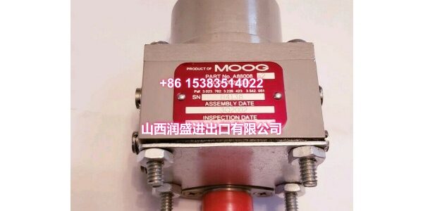
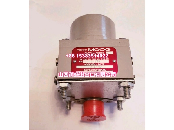
- Model: MOOG -002F-5
- OEM: MOOG
- Category: Two-Stage Servo Valve
- Core Function: Delivers high-flow, high-pressure hydraulic control for demanding industrial servo applications.
- Key Specs: 350 bar Max Pressure, D656 Series, -002F-5 Configuration
Technical Overview & Field Application
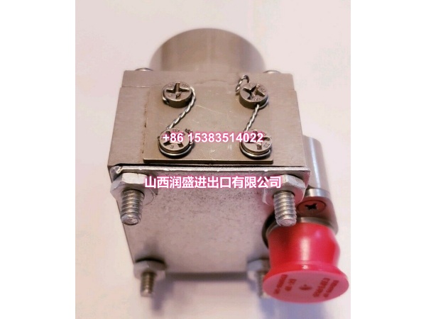
Heavy-duty hydraulic systems demand valves that can handle extreme pressure without sacrificing response. The MOOG is built for this exact challenge. It operates reliably at pressures up to 350 bar, making it ideal for metal forming, injection molding, and heavy press applications where standard valves fail.
This unit belongs to the high-performance D656 series, engineered for precise flow control under heavy loads. The “-002F-5” suffix defines its specific flow rating, spool configuration, and electrical interface. Getting this exact match is critical. A mismatched suffix means incorrect flow capacity or incompatible control signals, leading to poor system performance or even damage.
Field engineers value its high-pressure tolerance and robust construction. It maintains tight spool positioning even when system pressure fluctuates wildly. This stability translates directly to better part quality in manufacturing and fewer unplanned stops for maintenance.
Essential Specifications
| Parameter | Specification |
|---|---|
| Max Operating Pressure | 350 bar (P, A, B Ports) |
| Product Series | |
| Configuration Code | -002F-5 |
| Valve Type | Two-Stage Servo Valve |
| Typical Flow Rating | High Flow (See OEM Data Sheet) |
| Mounting Interface | ISO 4401 (Size Dependent) |
| Control Signal | Analog (Voltage/Current) |
| Operating Temp | -20°C to +80°C (Oil) |
| Cleanliness | ISO 4406 <15/12 Recommended |
| Seal Material | FPM (Viton) Standard |
Quality Assurance Protocol
Every MOOG is validated to ensure it meets the rigorous demands of high-pressure servo control. We don’t just check if it moves; we verify how it performs under stress.
- High-Pressure Leak Test: Each valve is pressurized to 350 bar to confirm zero external leakage and acceptable internal bypass.
- Flow Curve Validation: We map the flow vs. command signal to verify linearity and confirm the “-002F” flow rating is accurate.
- Spool Response Check: Step response tests ensure the valve reacts within spec, confirming no stiction or mechanical binding in the main stage.
- Coil Resistance Check: Electrical windings are measured to verify they are within tolerance, preventing future driver failures.
Note: Valves showing hysteresis >3% during testing are rejected. In high-pressure systems, hysteresis causes positioning errors that compound over time.
Engineer’s Installation / Replacement Notes
Verify the “-002F-5” suffix matches your old valve exactly. The “F” indicates a specific pressure rating and seal material. Substituting a different letter can lead to seal failure at 350 bar or incorrect flow characteristics.
- Oil Cleanliness is Non-Negotiable: At 350 bar, even small particles can score the spool. Ensure your system filtration is ISO 4406 <15/12 or better before installing this valve. Flush the lines if replacing a failed unit.
- Torque the Mounting Bolts Correctly: High pressure creates significant force on the valve body. Use a calibrated torque wrench and follow the OEM crisscross pattern. Uneven clamping causes internal leakage and spool binding.
- Check the Return Line Pressure: If your T-port return pressure exceeds 50 bar, you must use an external drain (Y-port). Backpressure on the T-port will shift the spool and destroy control accuracy.
- Warm-Up Cycle: After installation, run the system at low pressure for 10-15 minutes. This allows seals to seat properly and oil to reach operating temperature before applying full 350 bar load.