Product Core Brief
- Model: IS200AEADH1AAA
- Brand: GE (General Electric)
- Series: Speedtronic Mark VI
- Core Function: Interfaces turbine sensors and actuators directly to the drive control system.
- Product Type: Input Terminal Board / PCB Assembly
- Key Specs: 12-Pin Connectors | Hardware Noise Filters | VME Rack Compatible
- Condition: New Surplus / Tested Original
Product Introduction
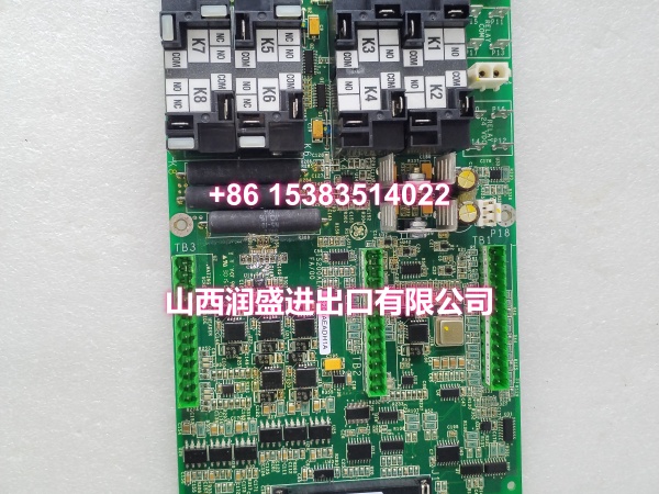
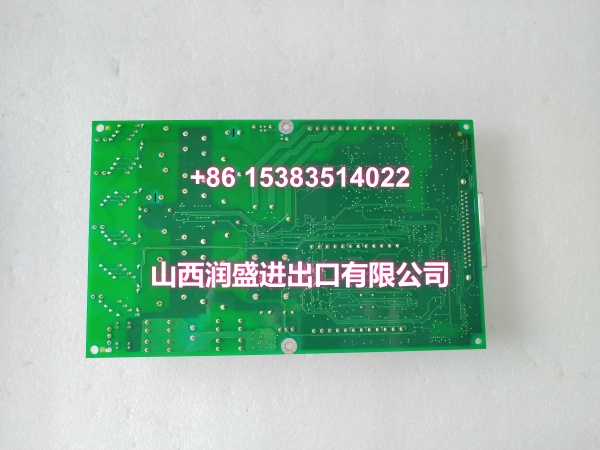
The GE is a dedicated input terminal board for the GE Mark VI Speedtronic turbine control system. This GE module connects directly to field sensors, eliminating the need for intermediate instrumentation.
Designed for high-noise environments, this GE board features built-in hardware filters to suppress high-frequency interference. It mounts securely in standard VME card racks and uses 12-pin connectors for reliable field wiring.
Key Technical Specifications
| Parameter | Value |
|---|---|
| System Compatibility | GE Speedtronic Mark VI |
| Module Type | Input Terminal Board (AEAD) |
| Connector Type | 12-Pin Pluggable Terminal Strips |
| Noise Suppression | Hardware Low-Pass Filters |
| Mounting Format | VME Card Rack (13 or 21 Slot) |
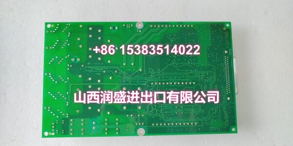
| Board Shape | Rectangular with Corner Mounting Holes |
| Primary Application | Gas/Steam Turbine Control |
| Secondary Application | Balance of Plant (BOP) Control |
| Data Transmission | Ethernet 10Base2 Interface |
| Signal Routing | Direct Sensor/Actuator Connection |
Quality Control Process
Terminal boards require meticulous electrical validation. We bench-test every GE using precision signal generators and oscilloscopes. We verify the hardware noise filters by injecting high-frequency interference and confirming signal attenuation. All 12-pin connectors are inspected for pin tension and continuity. We also inspect the PCB for thermal damage or cold solder joints. Each board ships in anti-static shielding with a traceable test report.
Replacement Pitfall Guide
❗ Hardware Filter Configurations: The J3 and J4 circuits on this GE have different filter breakpoints (500 rad/sec vs. 72/500 rad/sec). Wiring a high-speed sensor to the wrong terminal block will distort your signal.
❗ Connector Seating Force: The pluggable 12-pin terminal strips require even pressure. Never use excessive force on one side. Misaligned pins will cause intermittent faults that mimic sensor failures.
❗ VME Backplane Alignment: When inserting this board into the rack, ensure the rear connectors align perfectly with the backplane. Forcing a misaligned board can bend backplane pins and require a costly chassis replacement.
❗ Cable Shield Grounding: Since this board bypasses intermediate panels, field cable shields must be terminated correctly at the terminal board. Poor shielding turns this I/O interface into an antenna for turbine electrical noise.
Keep these in mind and you’ll cut 90% of rework time.
Compatibility Matrix & Benchmarks
| Original Model | Replacement / Successor Model | Compatibility Level | Migration Notes |
|---|---|---|---|
| IS200AEADH1ABA | Direct Drop-In | Verify revision suffix compatibility | |
| IS200AEADH4ADA | Needs Adaptation | Different filter config, check pinout | |
| IS200AEADH1ACA | Protocol Match | Same series, verify VME slot location |
- Filter Response: Single-pole and two-pole hardware attenuation.
- Wiring Density: Multiple 12-pin strips per rectangular PCB.
Need me to pull up the terminal block pinout diagram for the J3 and J4 filter circuits?