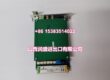
Product Core Brief
- Model: T8431
- Brand: ICS Triplex / Rockwell Automation
- Series: Trusted TMR Safety System
- Core Function: Acquires and processes analog field signals for safety-critical logic evaluation using Triple Modular Redundancy.
- Product Type: Trusted TMR Analog Input Module
- Key Specs: 24 Vdc | TMR Architecture | High-Resolution ADC | SIL3 Certified
- Condition: New Original (New Surplus)
Product Introduction
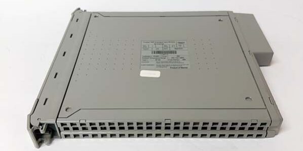
The is a high-integrity analog input module specifically engineered for the Trusted TMR (Triple Modular Redundancy) safety system. It serves as the critical sensing interface for continuous process variables, converting field signals into reliable digital data for safety logic evaluation.
Built on the Trusted TMR platform, the utilizes three synchronized processor fault containment regions to execute identical operations and perform majority voting on internal operations. This architecture ensures that even in the event of internal component failures, the module continues to provide accurate and reliable analog signal monitoring without nuisance alarming, making it ideal for SIL3 safety applications in oil & gas, power generation, and chemical processing.
Key Technical Specifications
| Parameter | Value |
|---|---|
| Module Type | Trusted TMR Analog Input Module |
| System Compatibility | ICS Triplex Trusted TMR Rack |
| Operating Voltage | 24 Vdc |
| Redundancy Architecture | Triple Modular Redundancy (TMR) with 2oo3 Voting |
| Safety Integrity Level | SIL3 (IEC 61508 / TÜV Certified) |
| Fault Handling | Automatic Fault Handling without Nuisance Alarming |
| Memory | Non-Volatile Memory for Program Storage |
| Diagnostics | Time-Stamped Fault Historian |
| Maintenance | Module Replacement without Program Down-Loading |
| Certifications | IEC 61508 SIL3, TÜV Certified |

ICS Triplex T8431
Quality Control Process (Engineer’s Perspective)
We don’t just box these and ship them. Here is our actual bench test workflow.
- Incoming Verification: We verify the serial number against ICS Triplex traceability records. A visual inspection checks for bent pins on the backplane connector and ensures the front panel status LEDs are intact.
- Live Functional Test: We mount the unit in a live TMR test rack. We inject calibrated analog signals and verify that all three redundant slices process the signal correctly and the majority voting logic produces the accurate digital value.
- Electrical Parameter Test: We perform a 500 V Megger test between the field input terminals and the backplane. Insulation resistance must exceed 10 MΩ. Ground continuity is verified.
- Diagnostic Injection Test: We intentionally inject signal out-of-range and wire-break conditions to confirm the module’s internal diagnostics trigger the correct fault codes and the time-stamped historian records the event accurately.
- Final QC & Packaging: The module is sealed in an anti-static bag with silica gel. A QC sticker showing the test date and technician initials is applied to the exterior.
Replacement Pitfall Guide
Field replacements on TMR safety systems are unforgiving. Watch out for these traps.
- Firmware Mismatch: ❗ Critical. A brand-new might have a newer firmware revision than your existing TMR CPU. The controller will block it with a configuration mismatch fault. Always check your system’s allowed firmware matrix before installing.
- TMR Voting Faults: ❗ Critical. The relies on three identical slices voting. If you are replacing a single slice, ensure the new module’s hardware revision and firmware match the other two slices. A mismatch will cause continuous voting failures and system faults.
- Terminal / Cable Incompatibility: Inspect the shielded cabling before connecting. Analog signals are highly susceptible to electrical noise; a broken shield or ground loop will cause erratic readings that mimic process alarms or trigger false diagnostics.
- Power Supply Headroom: Verify your external 24 Vdc field power supply has adequate headroom. While this module is low-power, a fully populated TMR rack with multiple AI modules can create significant cumulative load during system boot.
- ESD Damage: Safety modules are highly sensitive to electrostatic discharge. Always wear a grounded wrist strap when handling the bare PCB. I’ve seen modules fail bench testing because they were handled on a dry winter day without protection.
Keep these in mind and you’ll cut 90% of rework time.

ICS Triplex T8431
Compatibility Matrix & Benchmarks
Compatibility
- ICS Triplex Rev A → Rev B : Direct Replacement — Verify firmware compatibility with TMR CPU.
- ICS Triplex T8431C → : Needs Adaptation — T8431C may have different threshold programming or diagnostic features; requires logic re-validation.
Benchmarks
- Voting Consensus: < 5 ms (for three-slice synchronization)
- Diagnostic Coverage: >99% (internal dangerous failure detection)
Need the wiring diagram for the analog inputs? I can pull up the termination schematic showing the shield grounding points and commoning configuration for the TMR slices.