Product Core Brief
- Model: FC-FANWR-24R
- Brand: Honeywell
- Series: Industrial Automation / FSC Controller
- Core Function: Provides active cooling and ventilation for control enclosures and HVAC systems.
- Product Type: 24V DC Fan Assembly Kit
- Key Specs: 24 VDC | Dual Fan + PCB | 4-Pole Connector | Status Readback
- Condition: New Original (New Surplus)
Product Introduction
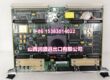
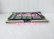
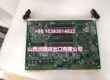
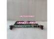
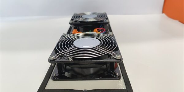
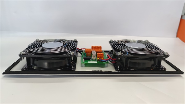
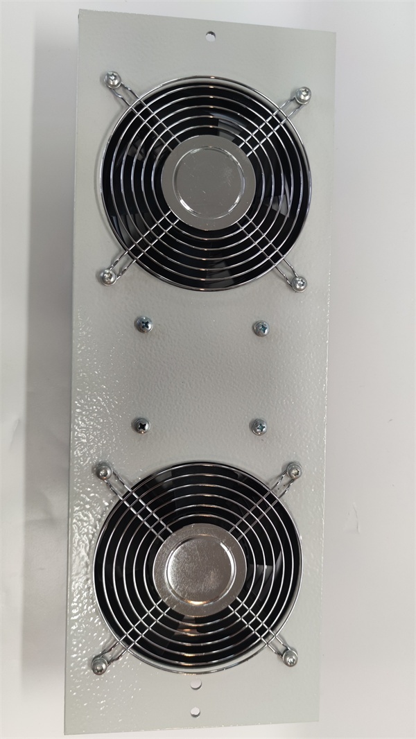
The is a specialized 24V DC fan assembly kit designed for industrial automation and process control environments. It consists of two fans and a printed circuit board (PCB) mounted on a plate, specifically engineered to ensure proper cooling and ventilation for critical control cabinets, HVAC systems, and enclosures.
This assembly features a 4-pole connector for both power and readback wiring, allowing the central controller to monitor fan status and detect potential cooling failures. With protective finger guards on both sides, the guarantees safe operation and reliable thermal management in demanding industrial applications.
Key Technical Specifications
| Parameter | Value |
|---|---|
| Module Type | Fan Assembly Kit |
| Operating Voltage | 24 VDC |
| Internal Components | Dual Fans + PCB on Plate |
| Connector Type | 4-Pole (Power & Readback) |
| Diagnostics | Fan Status Signal Generation |
| Safety Features | Finger Guards on Both Sides |
| Dimensions | 12.7 cm x 12.7 cm x 12.7 cm |
| Weight | 0.8 kg |
| Origin | United States |
| Application | HVAC, Enclosures, Process Control |
Quality Control Process (Engineer’s Perspective)
We don’t just box these and ship them. Here is our actual bench test workflow.
- Incoming Verification: We verify the serial number against Honeywell’s traceability records. A visual inspection checks the fan blades for cracks, ensures the finger guards are securely fastened, and verifies the 4-pole connector pins are straight.
- Live Functional Test: We apply 24 VDC to the assembly. We verify that both fans spin up smoothly without excessive vibration or bearing noise, and confirm that the PCB generates the correct readback status signal.
- Electrical Parameter Test: We measure the current draw of the dual-fan assembly to ensure it falls within the expected operating range. Continuity of the status readback circuit is verified.
- Mechanical Inspection: We verify the mounting plate is free of warping and that all fasteners are properly torqued.
- Final QC & Packaging: The module is sealed in an anti-static bag. A QC sticker showing the test date and technician initials is applied to the exterior.
Replacement Pitfall Guide
Field replacements on cooling systems are unforgiving. Watch out for these traps.
- Readback Wiring Mismatch: ❗ Critical. This module uses a 4-pole connector. If you only wire the power pins and ignore the readback pins, the controller will not receive the fan status signal and may trigger a false “Cooling Failure” alarm. Always verify the pinout against the system manual.
- Grounding Requirement: The assembly housing must be properly grounded to ensure electrical safety and prevent EMI interference with nearby sensitive I/O cards.
- Airflow Direction: Verify the airflow direction before installation. Installing the fan assembly backwards can create positive pressure in the cabinet, drawing dust into the controller rather than exhausting hot air.
- Voltage Verification: Confirm your cabinet’s power supply is delivering a stable 24 VDC. Undervoltage can cause the fans to spin slowly, leading to inadequate cooling and premature bearing failure.
- ESD Damage: The onboard PCB is sensitive to electrostatic discharge. Always wear a grounded wrist strap when handling the connector or PCB.
Keep these in mind and you’ll cut 90% of rework time.
Compatibility Matrix & Benchmarks
Compatibility
- Honeywell FC- Rev A → FC- Rev B : Direct Replacement — Verify readback signal compatibility.
- Honeywell FC-FANWR-24 → FC- : Verify mechanical dimensions and connector pinout before substitution.
Benchmarks
- Fan Spin-Up Time: < 2 seconds (from 24 VDC applied to nominal RPM)
- Readback Signal Response: < 500 ms (from fan stall to controller alarm)
Need the 4-pole connector pinout diagram for the ? I can pull up the wiring schematic showing the power and readback terminal assignments so you can connect it correctly.