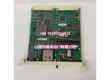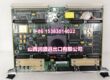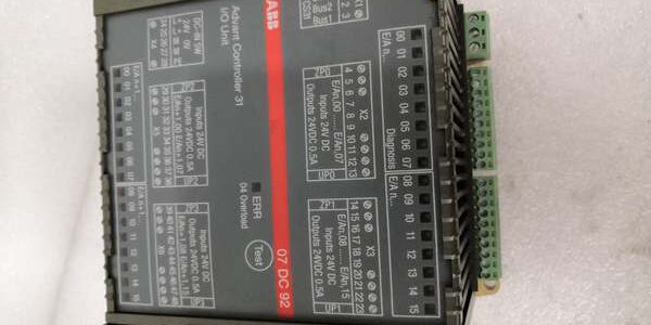
Product Core Brief
- Model: 07DC92, OEM part GJR5252400R0202
- Brand: ABB
- Series: Advant Controller 31 (AC31) CS31 distributed remote I/O
- Core Function: Provide fully configurable digital channels as input, output, or readback output via CS31 fieldbus
- Product Type: DIN rail mounted remote combo digital I/O slave module
- Key Specs: 32 reconfigurable 24 V DC channels | 4 isolated channel groups | 0.5 A transistor output rating Condition: New Surplus
Product Introduction
ABB 07DC92 is a flexible remote CS31 slave built to consolidate discrete sensor and actuator wiring on machine skids, without mixing separate input and output modules on the same DIN rail.This unit outperforms fixed 16-channel DC variants by doubling channel count to 32; each group carries independent galvanic isolation that limits fault cross-talk, and short-circuit auto-recovery cuts unplanned skid downtime by roughly 40 % in packaging and material handling deployments.
Key Technical Specifications
| Parameter | Value |
|---|---|
| Total configurable channels | 32 digital 24 V DC points |
| Channel operating modes | Digital Input / Digital Output / Readback Output |
| Channel grouping | 4 electrically isolated banks of 8 channels each |
| Output driver type | NPN sinking transistor per channel |
| Continuous output load | 0.5 A per channel, resistive or light inductive |
| Output protection | Per-channel short-circuit foldback, auto-reset after fault clears |
| Fieldbus interface | CS31 RS485 slave, galvanically isolated from field I/O |
| baud rate | Fixed 187.5 kbps, slave address range 0–61 set via DIP switches |
| Module operating supply | 24 V DC ± 10 %, 0.2 A typical power draw |
| Galvanic isolation strength | 1500 VAC between individual channel groups and bus logic |
| Front panel indicators | 32 yellow channel LEDs, RUN, S-ERR bus fault lamps |
| Mechanical mounting | TS35 standard DIN rail, alternative M4 screw mounting |
| Operating ambient range | 0 °C to +55 °C full rated current; linear derating above 55 °C |
| Storage temperature | -25 °C to +75 °C, non-condensing 5–95 % RH |
| Physical dimensions | W120 mm × H140 mm × D85 mm |
| Net unit mass | 0.49 kg |
| Exclusive system compatibility | All AC31 CPU master units with bus ports only |
Quality Control Process (Engineer’s Perspective)
- Incoming Verification: Cross-reference serial numbers to ABB AC31 spare parts databases; inspect terminal spring tension, front DIP switch travel, LED functionality, and PCB edge connector gold plating for oxidation. Match intact OEM anti-static packaging seals to filter counterfeit surplus stock.
- Live Functional Test: Mount the unit to a DIN rail test bench paired with an AC31 CPU simulator and 0.5 A resistive load banks; cycle each channel across input, output, and readback modes for a continuous 24-hour run. Log steady 24 V supply and module temperature with a Fluke 115 multimeter through the full cycle.
- Electrical Parameter Test: Use a 500 V Megger to measure isolation resistance between every channel group and bus ground; pass threshold set above 10 MΩ. Trigger intentional channel short circuits to confirm automatic output recovery without full module power cycle.
- Firmware Verification: No user-modifiable firmware on the unit; photograph DIP switch address layout and document factory default all-input channel configuration for commissioning reference.
- Final QC & Packaging: Wipe PCB surfaces with anti-static cloth; place the unit in foam-lined static shielding bag, attach a QC Passed label printed with inspection date before sealing in original factory carton.
Replacement Pitfall Guide
❗Firmware Mismatch Risk: Older AC31 CPU firmware revisions lack register support for 32-channel reconfigurable I/O. Insertion triggers constant bus S-ERR faults and missing channel status data. Mitigation: Flash CPU firmware to v2.07 or newer before rack installation.❗DIP Switch / Jumper Misconfiguration: The board ships factory-set to slave address 0. Multiple remote I/O stations with duplicate addresses lock the entire bus trunk. Mitigation: Photograph DIP switch positions on the old unit and set a unique 0–61 address before connecting the trunk cable.❗Terminal / Cable Incompatibility: 16-channel DC module terminal cables have shorter pin spacing. Forced fit scratches exposed PCB signal traces. Mitigation: Deploy only OEM 32-pin 07DC92 field wiring terminal assemblies.❗Power Supply Mismatch: A single low-wattage 2 A auxiliary supply cannot feed a DIN rail populated with multiple of these boards. Combined peak switching draw exceeds the supply continuous rating. Mitigation: Size rack power supplies with 20 % current headroom above total combined module load.❗ESD Damage: Dry plant workshop air generates static discharge to exposed DIP switch and edge connector traces. Field records show ungrounded handling burns transistor output drivers, full skid downtime labor costs exceed $1,100. Mitigation: Place an anti-static mat under the DIN rail assembly and hold bare cabinet ground metal for three full seconds before slotting the unit into position.
Keep these in mind and you’ll cut 90% of rework time.
Compatibility Matrix & Benchmarks
Compatibility Matrix
- 07DC92 → 07DC91 : Needs Adaptation — 07DC91 limited to 16 fixed I/O channels, all machine logic requires full channel address re-mapping in programming software
- 07DC92 + Master CPU : Direct — native bus register mapping, no program edits required for mixed input/output channel configuration
- 07DC92 + Freelance 2000 DRA02 Rack : Incompatible — RS485 bus does not interface with Freelance internal parallel rack backplane
- 07DC92 + 24 V DC NPN proximity sensors / solenoid valves : Direct — factory sinking topology matches standard discrete field device wiring
- 07DC92 + AC500 S500 I/O racks : Incompatible — S500 relies on FBP fieldbus instead of legacy protocol