Product Core Brief
- Model: VT–1-23/W-08-0-0, OEM part number R900955334
- Brand: Bosch Rexroth (Indramat Division)
- Series: VT- programmable digital hydraulic NC axis controller family
- Core Function: Execute full closed-loop position, speed, and pressure control for one hydraulic servo axis, exchange motion setpoints and fault diagnostics via PROFIBUS DP to host PLC systemsIndramat U…
- Product Type: Wall-mount single-axis digital hydraulic motion controller, series 23 hardware revision, 8-channel digital I/O terminal block, no auxiliary option card suffix
- Key Specs: 1 independent hydraulic control axis | PROFIBUS DP fieldbus | Wall-mount W housing | 8 digital DI/DO | 2 analog ±10V proportional valve outputs
- Note: OEM active production; factory-new surplus and fully bench-calibrated refurbished inventory available. Designed for hydraulic press, machine tool and semiconductor forming axis control stacks.
Key Technical Specifications
- Controlled Axis Count: 1 dedicated hydraulic closed-loop axis
- Hardware Series Revision: Series 23 base PCB layout
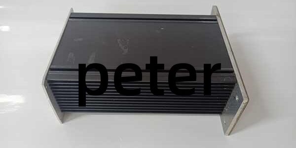
- Mount Form Factor: W = wall-mount aluminum heat sink chassis
- Digital I/O Allocation: 8 universal digital inputs + 8 digital outputs, 24VDC sink/source compatible
- Fieldbus Interface: PROFIBUS DP slave, standard 9-pin D-Sub connector
- Analog Valve Outputs: 2 current output channels, max 500Ω load resistance, ±10V proportional drive range
- Encoder Interface: 5VDC incremental encoder supply, max 200mA encoder feed, 250kHz maximum input frequency
- Analog Sensor Inputs: 4 differential analog voltage inputs for pressure/displacement transducers
- Onboard Memory: 1MB Flash EPROM for NC motion programs, 256KB RAM, 8KB battery-backed EEPROM for axis parameter storage
- Processor Core: MC68376 32-bit real-time motion CPU
- Supply Voltage: 18–36VDC unregulated cabinet DC rail, nominal 8W total power draw excluding field devices
- Programming Software Compatibility: WIN-PED v6 / v7 PC commissioning tool via RS232 service portManualsLib
- Operating Ambient Temp: 0°C to +50°C continuous cabinet operation; condensation acclimation required after cold storage
- Mechanical Dimensions: 71mm W × 155mm H × 204mm D, unit weight 1.0kg
- Compliance Standards: CE, UL, SEMI S2, EN61000 EMC industrial noise immunity certified
Product Introduction
This wall-mounted digital hydraulic controller runs three nested PID control loops for position, velocity and clamping pressure on single hydraulic servo axes used in precision press and substrate forming equipment. PROFIBUS DP communication eliminates hardwired analog setpoint wiring between the hydraulic axis and upper-level PLC logic.Dual proportional valve outputs drive Rexroth 4WRPEH and 4WREE servo valves, while onboard encoder and pressure transducer inputs provide closed-loop feedback without external signal conditioning hardware.
QA & Testing SOP (Transparency Building)
- Incoming Inspection: Cross-reference serial number against Rexroth OEM vital product databases; visual scan for dented heat sink fins, corroded D-Sub bus connectors, swollen backup battery, and cracked terminal block plastic. All RS232 and PROFIBUS pin wiring assignments photographed pre-test.
- Live Bench Testing: Mount unit to insulated wall-mount test fixture paired with a 4WREE hydraulic servo valve and linear displacement encoder; run continuous 24-hour cyclic position/pressure profile matching production press motion cycles. Fluke signal calibrator verifies analog valve output linearity and digital I/O switching timing.
- Communication & Memory Testing: Establish PROFIBUS DP master-slave link at 1.5Mbps baud rate; upload/download full NC motion program libraries to validate 1MB Flash read/write integrity, record EEPROM axis parameter retention over 12-hour power-off cycles.
- Analog Loop Calibration: Trim gain/offset for the two proportional valve output channels to OEM factory tolerance; validate encoder input frequency response up to 250kHz full scale without signal aliasing.
- Final QC & Packaging: Replace aged lithium backup battery during refurbishment cycles; seal unused D-Sub ports with OEM dust caps, wrap unit in static-dissipative foam, affix printed QC tag with analog linearity and PROFIBUS communication test metrics before sealed anti-static bag packaging.
Installation Pitfalls & Guide (Engineer to Engineer)
❗ Housing Mount Variant Mismatch Risk: This W wall-mount chassis cannot clip to standard DIN rail racks. M-series DIN rail VT- variants use different terminal block pin assignments and heat sink airflow geometry; direct cross-swap requires full hydraulic valve and fieldbus cable rework. Photograph original wall mounting hole layout before controller removal.❗ PROFIBUS DP Address Conflict Risk: Multiple units sharing one DP trunk require unique station addresses set via internal software parameters (no hardware DIP switches). Duplicate addresses trigger complete bus lockout and loss of all axis motion setpoint communication. Export full bus address mapping from the host PLC pre-replacement.❗ Analog Valve Load Overlimit Hazard: Proportional valve output channels are rated for maximum 500Ω load resistance. Low-impedance servo valve coils below this threshold create output current saturation and unstable pressure loop oscillation during clamping cycles.❗ Condensation Short-Circuit Risk: Cold-stored units moved into warm humid cabinets form internal condensation within 2 hours. Allow 4-hour temperature acclimation before applying 24VDC supply to prevent PCB trace corrosion and permanent CPU damage.❗ Catastrophic ESD Damage Risk: Unshielded incremental encoder input ASICs sustain permanent leakage damage from ungrounded handling; certified ESD wrist strap and conductive anti-static mat mandatory before touching terminal blocks or exposed D-Sub connector pins.4-Step Replacement Guide:
- Pre-install: Execute machine lockout-tagout, depressurize hydraulic manifold fully, export all axis PID gain, limit and NC motion program sets via WIN-PED software and PLC HMI.
- Removal: Disconnect PROFIBUS DP, RS232 service, analog valve, encoder and digital I/O terminal cables one at a time; unfasten four wall mounting bolts evenly, lift unit straight off the mounting surface and rest on ESD foam pad. Record all terminal wire pin assignments.
- Install: Align replacement unit to original wall hole pattern, torque mounting fasteners to OEM specified torque value, re-terminate all field wiring to matching terminal pinouts following recorded layout, separate analog valve cables and digital bus trunking per EMC wiring rules.
- Power-on Test: Restore cabinet 24VDC supply, confirm power and PROFIBUS status LEDs illuminate steady green, upload saved axis parameter set, run 30-minute cyclic position/pressure motion test to validate stable closed-loop response and fault diagnostic reporting over DP bus.
FAQ (Frequently Asked Questions)
Q: Can this wall-mount unit replace DIN rail M-series VT- variants on identical hydraulic press racks without parameter rework?A: No out-of-box cross-compatibility. M-series DIN rail hardware shares identical firmware but uses different terminal block pin mapping and thermal airflow limits; full cable re-termination and axis loop gain retuning are required after swap.Q: Does this hydraulic axis controller support hot-swapping while cabinet 24VDC supply and PROFIBUS DP bus remain energized?A: The terminal block power and signal pins lack staged hot-swap power sequencing. Live disconnection injects voltage transients into analog valve drive circuits, corrupting EEPROM stored axis PID parameters and risking permanent proportional valve coil saturation damage. Full cabinet DC power lockout is mandatory before cable disconnection.Q: What warranty separates factory-new surplus stock from calibrated refud VT-/W-08-0-0 units?A: Factory-new Rexroth-certified surplus carries a 12-month industrial warranty covering Flash memory corruption, analog output drift and PROFIBUS communication failure. Refurbished calibrated units ship with a 6-month limited functional warranty; aged lithium backup batteries and electrolytic filter capacitors exhibit gradual performance degradation under continuous cabinet heat.Q: Will swapping this hydraulic controller erase stored axis clamping pressure limits and motion NC programs?A: All motion sequences, PID gains and transducer scaling values reside in the unit’s onboard Flash and EEPROM memory, independent of the host PLC. Export a full parameter and program backup via WIN-PED software before disassembly to avoid complete axis retuning post-install.Q: Can this hardware operate with older WIN-PED v5 commissioning software released prior to 2008 without firmware updates?A: Series 23 hardware revision requires WIN-PED v6 minimum software version; v5 builds lack the device description file for PROFIBUS DP parameter mapping, leading to incomplete axis loop tuning visibility and missing fault diagnostic registers.Q: What expected service window applies to factory-new versus refurbished controllers in 24/7 high-volume press production environments?A: Factory-new units target scheduled backup battery and input filter capacitor replacement at 44,000 operating hours. Refurbished variants degrade at 34,000 hours; reused electrolytic capacitors lose capacitance over time, widening analog valve output noise floor and triggering unstable hydraulic axis hunting during precision clamping cycles.Q: What functional difference separates the 0 suffix base model and P-suffix variants of the same series 23 hardware?A: This 0 suffix unit has no auxiliary analog monitoring option card populated on the PCB; P-suffix variants add extra pressure transducer analog input channels for dual-load cell clamping force monitoring, requiring different terminal block wiring layouts for multi-sensor hydraulic loops.