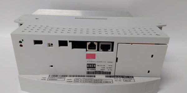
Product Core Brief
- Model:
- Brand: KUKA Robotics (Germany)
- Series: Size 1 Servo Drive Family ⚠️ EOL, only original surplus & factory refurbished stock available
- Core Function: High-response closed-loop torque, speed and position control for ultra-light robot wrist axes, small external positioner and auxiliary servo motors; receives real-time trajectory commands via Interbus from cabinet CCU, outputs variable three-phase power to low-power KUKA servo motorsManualsLib
- Product Type: Cabinet-mounted single-axis robot dedicated servo amplifier
- Key Specs: 4 A continuous / 8 A peak output current | 400 VAC three-phase DC bus supply | Max 0.8 kW output power | Interbus IN/OUT daisy-chain bus | Compatible with KR C2 / KR C4 robot controllers | OEM part number: 00-122-284 | Condition: New Original Surplus / Refurbished
Product Introduction
ThKA is the smallest Size 1 single-axis servo drive exclusively built for KR C2 and KR C4 robot control cabinets, deployed on tiny wrist joints, tool changer auxiliary axes and light-duty positioner axes of 6-axis industrial manipulators. It communicates with the central CCU via Interbus to execute micro-precision motion trajectories, while continuously reading proprietary resolver/incremental encoder feedback to maintain micron-level positioning accuracyManualsLib.This entry-level low-current unit sits at the bottom of the performance tier, below -16, -32 and heavy-load -48/64 drives. It uses passive natural convection aluminum heat sinking without auxiliary cooling fans to cut cabinet maintenance points and running noise. OEM reliability testing records an MTBF of 105,000 operating hours under standard 40 °C cabinet ambient. Unlike generic third-party servo drives, it uses proprietary Interbus protocol and motion algorithms fully matched to KUKA robot mechanical parameters.
Key Technical Specifications
| Parameter | Value |
|---|---|
| Rated Continuous Output Current | 4 A continuous; 8 A peak short-term overload (1s acceleration) |
| DC Bus Input Range | 0–565 / 0–675 VDC (derived from cabinet 3-phase 400 VAC mains rectifier) |
| Nominal Rated Output Power | 0.8 kW, dedicated for ultra-light wrist & auxiliary axes |
| Cascaded Control Modes | Torque inner loop, speed mid loop, position outer full closed-loop control |
| Communication Bus | Interbus (X13 IN / X14 OUT) daisy-chain multi-drive rack topology |
| Motor Feedback Support | KUKA proprietary resolver and sine/cosine incremental encoder interfaces |
| Cooling Architecture | Passive natural convection heat sink, no built-in cooling fan |
| Enclosure Protection Rating | IP20, internal cabinet mounting only; no outdoor field installation approval |
| Operating Ambient Temp | 0 °C to +55 °C; storage -25 °C to +70 °C |
| Integrated Safety Protection | Overcurrent, short-circuit, overvoltage, undervoltage, overheat, encoder loss, Interbus communication timeout, motor overtemperature |
| Standard OEM Part Code | 00-122-284 (universal KR C2 / KR C4 compatible version) |
| Cabinet Form Factor | Standard Size 1 vertical rack slot interchangeable with -16 / -32 |
| Main Connector Definition | X1: DC bus power supply; X2: 3-phase servo motor power; X8: External brake resistor; X13/X14: Interbus communication; X3: Motor temperature sensor + encoder feedback |
| Unit Weight | Approx. 1.9 kg |
| Compliance Certifications | CE, UL AWM, RoHS, SIL2 robot functional safety qualified |
Quality Control Process (Engineer’s Perspective)
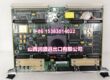
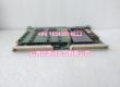
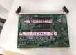
- Incoming Verification: Cross serial numbers against official KUKA factory production manifests to filter counterfeit aftermarket copies. Visually inspect Interbus RJ45 ports, motor power terminal screw blocks, heat sink fin integrity, and front panel status LED lenses for scratches or deformation.
- Live Functional Test: Mount drive inside a KR C4 test cabinet paired with matched KSP600 central DC power supply and tiny wrist-axis KUKA servo motor. Run a 24-hour continuous soak cycle with cyclic robot wrist trajectory programs; log Interbus communication stability, output current ripple and thermal overload trigger thresholds hourly.
- Electrical Parameter Test: Use a 500 V Megger insulation tester to verify isolation resistance between all power terminals and chassis ground; pass threshold >10 MΩ. Validate sub-2µs rapid short-circuit latch protection and motor temperature sensor fault detection response.
- Firmware Verification: Read drive firmware revision via KUKA WorkVisual commissioning software; record build version and cross-check against robot controller software compatibility matrix. Photograph Interbus termination DIP switch positions for on-site commissioning reference records.
- Final QC & Packaging: Place drive inside anti-static ESD foam packaging with factory plastic dust caps on all connectors. Affix dated QC Pass sticker listing insulation resistance test data and total soak runtime before warehouse storage.
Replacement Pitfall Guide
❗ Controller Compatibility Mismatch Risk:he only supports KR C2 and KR C4 cabinet platforms. It cannot be installed into newer KR C5 cabinets using KSD2 series drives; mixing drive generations triggers permanent Interbus communication failure and robot emergency stop lockout.❗ Interbus Termination Jumper Misconfiguration Risk: The last drive in an Interbus daisy-chain rack requires enabled termination resistor via onboard DIP switch. Unmatched termination creates signal reflection noise and random axis following error alarms during high-speed robot wrist movement.❗ Drive Current Rating Swap Risk: Mechanically interchangeable with -16 / -32, but repng with higher-current models requires full re-calibration of axis current limit parameters via WorkVisual software; unmodified parameters cause unnecessary overload fault trips during light-load wrist motion.❗ DC Bus Power Headroom Miscalculation Risk: A fully ed draws peak 4.9 A from cabinet DC bus. When multiple axes operate simultaneously, size the KSP series central power pack with 20% power overhead; underrated power supplies trigger undervoltage safe stop protection.❗ ESD Damage Risk: Exposed X2 motor power and X13 Interbus ports are highly ESD sensitive during cabinet disassembly. Use a grounded anti-static wrist mat during drive swapping in low-humidity workshop environments; static discharge corrupts internal control PCB and generates intermittent encoder signal dropout faults.Keep these in mind and you’ll cut 90% of rework time.
Compatibility Matrix & Benchmarks
Compatibility Matrix
- KR C2 / KR C4 Robot Controller Cabi → : Direct Replacement — Native Interbus rack topology, zero cabinet mechanical modification required
- KUKA Ultra-Light Wrist/Auxiliary Servo Motors (≤0.8 → : Native Matched — Proprietary encoder/resolver feedback pinout fully compatible
- -16 (16A Small Servo Dr → : Needs Adaptation — Rack slot fits, robot axis current limit and motion gain parameters must be fully re-tuned via WorkVisual
- KSD2 Series (KR C5 New Generation Dri → : Incompatible — Different backplane bus protocol and cabinet mechanical locking structure, cannot intermix hardware
Benchmarks
- Full tiny wrist axis position loop response bandwidth: 1.6 kHz (nominal 400 VAC mains supply, ultra-low inertial wrist load)
- Short-circuit IGBT shutdown delay: <2 µs to protect motor windings and internal power semiconductors
- Continuous standby power consumption: 18 W; full rated 4 A output steady-state power draw: 0.75 kW