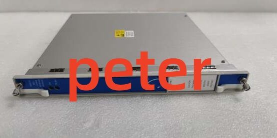
Product Core Brief
- Model: 3500/04-01, assembly PN 136719-01
- Brand: Bently Nevada (Baker Hughes)
- Series: 3500 Machinery Protection TSI Rack System
- Core Function: Dedicated single-slot earthing module that establishes a stable intrinsically safe (IS) reference ground for racks fitted with internal IS barrier I/O cards
- Product Type: Single-slot hot-swappable IS barrier grounding auxiliary module
- Key Specs: Dedicated IS ground bus connection | 1.8W typical power draw | Mandatory for internal barrier hazardous area layouts
- Note: Active OEM production auxiliary hardware; factory-new and refurbished surplus available. Any rack using internal IS barrier I/O cards requires this unit installed in an empty standard module slot.
Key Technical Specifications
- Slot requirement: Occupies one full single-width standard module slot; reduces usable monitor channel slots from 14 to 13 on full-size 19-inch racks, 7 to 6 on mini racks
- Power consumption: 1.8W continuous load, fed directly from rack 24VDC backplane bus
- Ground circuit design: Isolated copper IS ground bus terminal block, separated from chassis protective earth to meet ATEX/Class I Div 2 intrinsic safety rules
- Hazardous compliance: Provides the mandatory low-impedance IS reference path required for all internal barrier transducer wiring circuits
- Galvanic isolation: 1500VAC separation between IS ground circuit and standard rack signal/power backplane traces
- Operating temperature: -30°C to +65°C standard ambient; conformal coated variant rated -40°C to +85°C offshore cabinet deployment
- Compatibility: Works with all full-size 3500/05 14-slot and mini 7-slot rack chassis; compatible with all internal IS barrier I/O modules
- Physical dimensions: Standard single 3500 rack slot footprint, unit weight 0.201kg, fully hot-swap rated
- Certifications: API 670, CE EMC, UL Class I Div 2, ATEX Zone 2 intrinsically safe compliance support
- Critical installation rule: Must be wired to a dedicated local IS earth electrode independent of cabinet safety ground to eliminate ground loop distortion of barrier-limited transducer signals
Product Introduction
This auxiliary ground module is a mandatory add-on for any 3500 rack equipped with internal intrinsically safe barrier I/O cards used in oil & gas, refinery, and chemical hazardous classified zones. It creates a noise-free dedicated reference ground to maintain barrier energy limiting performance for field-mounted proximity, velocity, and temperature transducers.Its primary field constraint is slot consumption. Installing the unit consumes one monitor slot, so rack layout planning must reserve empty space for this ground card during initial cabinet design for hazardous area deployments.
QA & Testing SOP (Transparency Building)
- Incoming Inspection: Cross-reference serial numbers against OEM production databases to reject counterfeit hardware. Complete physical audit of PCB ground bus traces, rear terminal earth screw lugs, and front panel OK status LED; capture timestamped photos of lug corrosion or broken ground traces.
- Live Power-On Testing: Mount the device in a calibrated test 3500 rack powered by a Fluke 115 24VDC supply. Run continuous 24-hour load test alongside simulated internal barrier I/O cards to validate stable power draw and zero ground loop voltage offset across IS signal circuits.
- Low-Impedance Ground Testing: Use a micro-ohmmeter to verify IS ground bus impedance <0.05Ω between the module’s rear terminal lug and rack barrier signal traces; confirm no leakage current between IS ground and chassis protective earth.
- Firmware & Config Backup: Flash the latest OEM compatible firmware revision, log exact version numbers. This module carries no user-configurable measurement parameters; only rack barrier layout mapping is documented offline.
- Final QC & Packaging: Perform continuity scan across all internal ground bus paths, attach serialized QC test tag with full ground impedance test timestamp, place unit in anti-static foam, seal inside ESD shielding packaging for transit.
Installation Pitfalls & Guide (Engineer to Engineer)
❗ Shared Earth Electrode Risk: Tying the module’s IS ground lug to the cabinet’s main protective safety ground creates large ground loop currents that degrade internal barrier energy limiting and produce erratic transducer signal readings in hazardous areas. Run a separate dedicated IS earth rod exclusively for this module.❗ Firmware Rev Mismatch Risk: Mismatched rack-wide firmware revisions trigger persistent backplane OK LED faults and break IS ground reference coordination with internal barrier I/O cards. Export full rack firmware stack before swapping the module; never deploy mixed revision firmware sets.❗ Slot Layout Oversight Risk: Forgetting to reserve a dedicated slot for this unit during rack design forces last-minute removal of critical vibration/temperature monitor channels to accommodate the ground card, cutting machinery protection coverage.❗ ESD Damage Risk: Ungrounded field tools touching rear IS ground terminal lugs discharge static and fracture thin PCB ground bus traces; OEM PCB replacement labor exceeds $1,400 for production hazardous-area hardware.❗ Missing Barrier Wiring Separation Risk: Failing to maintain the required 50mm physical separation between hazardous IS field wiring and safe-area control cabling negates ATEX/Class I Div 2 certification compliance regardless of proper 3500/04-01 grounding.
4-Step Replacement Guide
- Pre-install: Attach ESD wrist strap, power down rack redundant power supplies and isolate facility AC/DC feeds, photograph rear IS ground lug wiring and record its dedicated earth electrode run, log active rack firmware revision set.
- Removal: Unlatch front panel extraction levers to disengage backplane pins, slide the unit straight out of its assigned rack slot without bending PCB edge connectors; disconnect the IS ground lug wiring from the rear terminal block.
- Install: Align the replacement unit’s backplane pins with the rack bus, slide fully into the reserved slot, squeeze extraction levers to lock contact pins, re-terminate the dedicated IS earth cable to the rear ground lug matching pre-replacement photos.
- Power-on Test: Restore rack power, confirm steady green OK LED on the module, measure IS ground bus impedance with a micro-ohmmeter, verify all internal barrier transducer channels show stable, noise-free readings before returning hazardous-area rotating machinery to automatic operation.
FAQ (Frequently Asked Questions)
Q: Does this unit support live hot-swap operation with the rack energized?A: Yes, the hardware is rated for hot-swap without full rack power loss. Existing internal barrier measurement channels retain partial signal limiting during swap, though full IS ground reference stability is temporarily degraded until the replacement unit locks into the backplane bus.
Q: Is this module required for racks without internal IS barrier I/O cards?A: No. Racks using only standard non-barrier monitor modules for general industrial non-hazardous zones do not need this earthing card; it is exclusively mandated for internal intrinsically safe barrier layouts.
Q: What warranty coverage applies to refurbished surplus inventory?A: Refurbished stock carries a 12-month functional warranty covering PCB ground bus continuity, backplane communication circuits, and terminal lug integrity; cosmetic scratches and minor lug surface oxidation are excluded from claims. Factory-new OEM units ship with a full 36-month manufacturer warranty.
Q: Will rack power cycling alter the IS ground reference performance of this module?A: No. The ground bus impedance and isolation barrier circuitry are passive hardware designs with no stored configuration data; power loss and re-energization do not shift IS reference potential.
Q: Does this module perform any vibration, temperature, or speed measurement functions?A: No. This is a purely auxiliary grounding accessory with no transducer signal conditioning, analog output, or alarm trip logic capabilities; it only provides a compliant IS ground path for barrier cards.
Q: Can multiple 3500/04-01 units be installed in a single rack with multiple internal barrier card banks?A: OEM design rules allow only one unit per rack chassis. A single dedicated IS ground bus serves all internal barrier I/O cards across all rack slots; extra copies create redundant ground loops and violate hazardous area certification limits.
Q: What happens if the module loses backplane communication mid-operation?A: The front panel OK LED switches to red fault status, and internal barrier channels experience signal offset drift. Hazardous area protection integrity is compromised, and operators receive rack-wide fault alarms via the Slot1 TDI communication module.